Layout
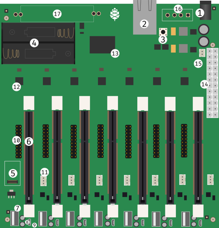
The Clusterboard with labels
| Label | Description |
|---|---|
| 1 | Barrel-type DC jack (6.3 mm outer diameter, 3.0 mm inner diameter) for a +5 V, 15 A power supply |
| 2 | Gigabit Ethernet port |
| 3 | Reset button, for all seven modules |
| 4 | Holder for two non-rechargeable 1.5 V AA-size batteries, providing backup for the real-time clock (RTC) on all modules |
| 5 | Connector for an eMMC module, for the first SOPINE or SOEDGE module |
| 6 | Slot for a SOPINE or SOEDGE module |
| 7 | USB 2.0 Type-A socket |
| 8 | MicroUSB Type-B USB 2.0 socket |
| 9 | Activity LED |
| 10 | 20-pin expansion connector |
| 11 | Three-pin connector for a lithium battery |
| 12 | RTL8211E Gigabit Ethernet PHY, with two status LEDs |
| 13 | Gigabit Ethernet Switch (RTL8370N) |
| 14 | 24-pin ATX Power Connector |
| 15 | Two-pin connector for a switch/button that turns on connected ATX power supply |
| 16 | 5 V power output for hard disk drives (optional) |
| 17 | Places for soldering two resistors (optional, for use with an ATX power supply that requires dummy load on 3.3 V and 12 V rails) |
For the part 4, please see the important note in the specifications page. For the part 11, please see the notes in the hardware revisions page. Parts 6 to 12 exist separately for each of all seven SOPINE or SOEDGE modules.
20-pin Expansion Connector
The 20-pin expansion connector is the part 10 described in the section above, available for each SOPINE or SOEDGE module. There is an unofficial description of the pinout in this forum thread. The unofficial pinout is also visible directly in this picture.
SOPINE Module
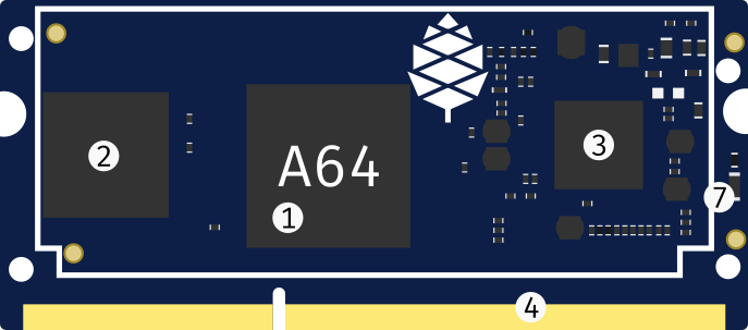
Front view of the SOPINE module with labels
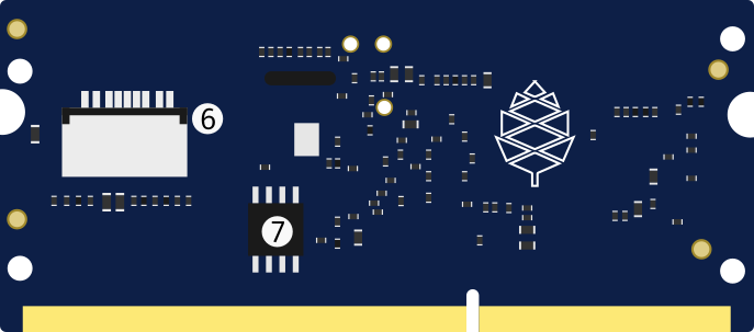
Rear view of the SOPINE module with labels
| Label | Description |
|---|---|
| 1 | A64 SoC |
| 2 | 2 GB of DDR3 RAM |
| 3 | AXP803 PMIC |
| 4 | Edge connector, the same as on SO-DIMM modules |
| 5 | Power LED |
| 6 | microSD card slot |
| 7 | SPI flash memory |
Table of contents