Flashing
This page explains how to flash an Ox64 board and a microSD card to boot the system. You will need a Linux computer, a serial UART adapter, the Ox64 board, and a microSD card.
Prepare images for flashing
Download the Ox64 images from the latest OpenBouffalo release. You may skip this step if you built your own images as per the instructions in the Building page.
$ mkdir -p ~/ox64/openbouffalo
$ cd ~/ox64/openbouffalo
$ wget https://github.com/openbouffalo/buildroot_bouffalo/releases/download/v1.0.1/bl808-linux-pine64_ox64_full_defconfig.tar.gz
$ tar -xvzf bl808-linux-pine64_ox64_full_defconfig.tar.gz
$ cd ~/ox64/openbouffalo/firmware
$ xz -v -d -k sdcard-pine64_ox64_full_defconfig.img.xz
$ mv sdcard-pine64_ox64_full_defconfig.img sdcard.img
Optional: create a combined SoC image
Use the following commands to combine m0_lowload_bl808_m0.bin, d0_lowload_bl808_d0.bin, and bl808-firmware.bin into a single image. This is mainly useful for troubleshooting (e. g. when using DevCube v1.8.4 or later).
$ cd ~/ox64/openbouffalo/firmware # if you downloaded pre-built images
 # or
$ cd ~/ox64/buildroot/output/images # if you built your own images

$ fallocate -l 0x800000 bl808-combined.bin
$ dd conv=notrunc if=m0_lowload_bl808_m0.bin of=bl808-combined.bin
$ dd conv=notrunc if=d0_lowload_bl808_d0.bin of=bl808-combined.bin seek=$((0x100000))B
$ cat bl808-firmware.bin >> bl808-combined.bin
Check that you have the required files for flashing
$ cd ~/ox64/openbouffalo/firmware # if you downloaded pre-built images
 # or
$ cd ~/ox64/buildroot/output/images # if you built your own images

$ ls -1 *808*.bin *.img
Expected files:
bl808-combined.bin– If you created the combined image.bl808-firmware.bin– OpenSBI and UBoot DTB files. Runs on the D0 core.d0_lowload_bl808_d0.bin– Startup code for the D0 core.m0_lowload_bl808_m0.bin– Startup code for the M0 core.sdcard.img– Kernel and root filesystem. Runs on the D0 core.
Set up your UART adapter
In this section we will configure and wire up a UART adapter in order to flash the Ox64. Choose one of the options below based on the hardware available to you; the first two are the most convenient since they minimize the number of times you will need to swap electrical connections.
Option 1: Raspberry Pi Pico
First, download the Raspberry Pi Pico firmware that allows it to act as a serial UART adapter:
$ mkdir -p ~/ox64/pico
$ cd ~/ox64/pico
$ wget https://github.com/Kris-Sekula/Pine64_Ox64_SBC/raw/main/uart/picoprobe.uf2
Put the Raspberry Pi Pico board into programming mode:
- Press the BootSel button
- Apply power by plugging the USB cable to PC
- Release the BootSel button
TP6 (located on the bottom of the Pico board) to any ground point (e. g. pin 28).The Pico will now appear as a USB mass storage device. Copy the UF2 file to program it:
$ cp ~/ox64/pico/picoprobe.uf2 /media/<user>/RPI-RP2
Next, connect the Ox64 board to the Pico according to the following wiring diagram:
| Ox64 | PI PICO | /dev/tty |
|---|---|---|
| uart0_Tx_GPIO14_pin1 | uart0_Rx_pin17 | ACM1 for flashing |
| uart0_Rx_GPIO15_pin2 | uart0_Tx_pin16 | ACM1 for flashing |
| Rxd_GPIO17_pin31 | uart1_Tx_pin6 | ACM0 for serial console |
| Txd_GPIO16_pin32 | uart1_Rx_pin7 | ACM0 for serial console |
| gnd_pin38 | gnd_pin38/3 | |
| vbus5v_pin40 | vbus5v_pin40 |
With the Pico flashed and wired as per the instructions above, we have access to two of the Ox64’s UART ports at the same time. This configuration eliminates the need to switch the physical connections for flashing or testing the system.
Reconnect the Pico to your computer’s USB port and verify that we have access to all the serial ports we need:
$ ls /dev/ttyACM*
Expected result:
/dev/ttyACM0connects to the D0 core’s (i.e. Linux’s) serial console/dev/ttyACM1is used for flashing (but also connects to the M0 core’s serial console)
Option 2: STM32 Bluepill
The Bluepill is an affordable STM32 development board, based on the STM32F103C8T6 chip. We can program it to act as a USB serial adapter, just like we did with the Raspberry Pi Pico.
The one catch is that you already need a serial adapter in order to program your Bluepill board. The good news is that you serial adapter does not have to be one from from the Compatible UARTs list. These programming instructions have been tested with a FT232RL adapter (which, notably, is listed as not supported on that list).
If you own an SWD-capable debugger (ST-Link, J-link, etc.) you can use that for programming the Bluepill as well, although instead of stm32flash console command you would be using openocd or other suitable software.
Install software to flash Bluepill. For Debian-based systems just install package from repository:
$ sudo apt install stm32flash
For Arch Linux systems, use the AUR repository:
$ mkdir -p ~/ox64/bluepill
$ cd ~/ox64/bluepill
$ git clone https://aur.archlinux.org/stm32flash.git
$ cd ~/ox64/bluepill/stm32flash
$ makepkg -si
Download the Bluepill Serial Monster firmware:
$ mkdir -p ~/ox64/bluepill
$ cd ~/ox64/bluepill
$ wget https://github.com/r2axz/bluepill-serial-monster/releases/download/v2.6.4/bluepill-serial-monster.hex
Put the Bluepill into programming mode:
- Set boot jumpers for booting from rom: Boot0=1, Boot1=0.
- Connect it to a USB-Serial adapter with A9 to Rx, A10 to Tx, GND to GND, 3v3 to Vcc.
- Apply power by plugging the USB cable to PC. Press the Reset button.
Find your USB serial adapter’s device path with ls /dev/ttyUSB* /dev/ttyACM* (or similar); for the rest of this section we will refer to it as /dev/tty[DEVICE]. Upload the firmware:
$ cd ~/ox64/bluepill
$ sudo stm32flash -w bluepill-serial-monster.hex /dev/tty[DEVICE]
After upload, set boot jumpers for boot from flash: Boot0=0, Boot1=0. Disconnect the USB serial adapter from both the PC and Bluepill board.
Next, connect the Ox64 board to the Bluepill according to the following wiring diagram:
| Ox64 | Bluepill | /dev/tty |
|---|---|---|
| uart0_Tx_GPIO14_pin1 | uart0_Rx_A3 | ACM1 for flashing |
| uart0_Rx_GPIO15_pin2 | uart0_Tx_A2 | ACM1 for flashing |
| Rxd_GPIO17_pin31 | uart1_Tx_A9 | ACM0 for serial console |
| Txd_GPIO16_pin32 | uart1_Rx_A10 | ACM0 for serial console |
| gnd_pin38 | GND | |
| vbus5v_pin40 | 5V |
With the Bluepill flashed and wired as per the instructions above, we have access to two of the Ox64’s UART connections at the same time. This configuration eliminates the need to switch the physical connections for flashing or testing the system.
Connect the Bluepill to your computer’s USB port and verify that we have access to all the serial ports we need:
$ ls /dev/ttyACM*
Expected result:
/dev/ttyACM0connects to the D0 core’s (i.e. Linux’s) serial console/dev/ttyACM1is used for flashing (but also connects to the M0 core’s serial console)/dev/ttyACM2(unused)
Option 3: Generic UART adapter
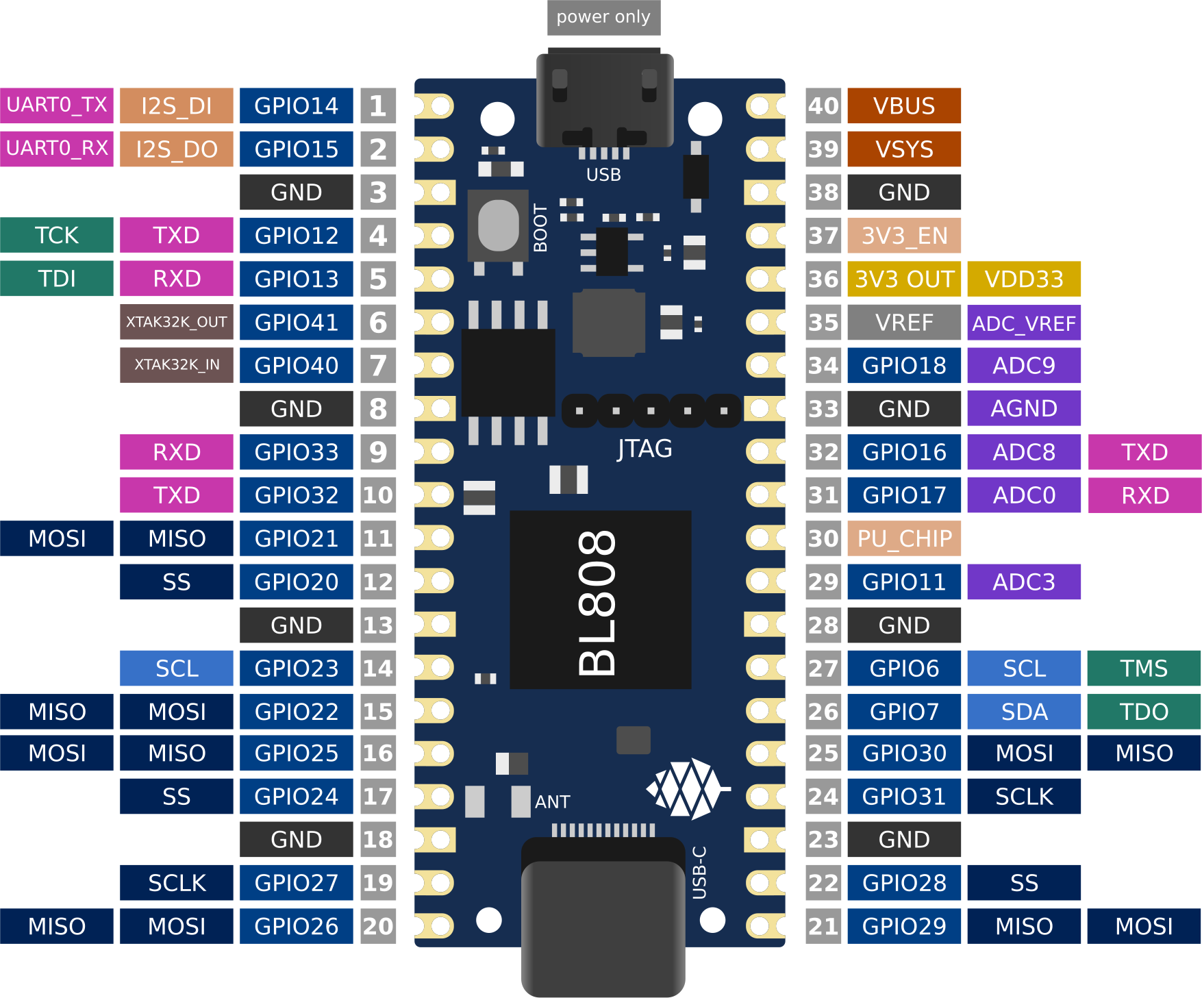
Ox64 pinout
Check that your serial adapter is on the Compatible UARTs list. You will (most likely) only have one serial interface available to you; unlike the previous options you will be using this same serial interface for both flashing and testing the system.
Find its device path with ls /dev/ttyUSB* /dev/ttyACM* (or similar); for the rest of this section we will refer to it as /dev/tty[DEVICE].
You will also need a way of powering your Ox64. If your serial adapter has a 5V line, you can connect it to VBUS (pin 40). Otherwise, you can connect either the micro-B or the USB-C port on the Ox64 to any 5V power supply.
Refer to the pinout image below. Connect your UART adapter as follows:
- RX -> UART0_TX / GPIO14 / pin 1
- TX -> UART0_RX / GPIO15 / pin 2
- GND -> any ground (e. g. pin 3)
Proceed with the instructions in the sections that follow, up to and including flashing_the_ox64 and flashing_the_microsd_card, but replace all occurrences of /dev/ttyACM1 with /dev/tty[DEVICE].
Next, power off the Ox64 and re-connect your UART adapter as follows:
- RX -> TXD / GPIO16 / pin 32
- TX -> RXD / GPIO17 / pin 31
- GND -> any ground (e. g. pin 33)
Then, follow the instructions in booting_for_the_first_time, but replace all occurrences of /dev/ttyACM0 with /dev/tty[DEVICE]. You should then have a working Linux system.
Download flashing tools
You have a choice of flashing software:
- DevCube: Bouffalo’s GUI-based closed source flashing tool
bflb-iot-tool: Bouffalo’s command line open source flashing tool- Blisp: Third party command line open source flashing tool
Installation: DevCube
Download the latest DevCube flashing tool from BouffaloLab’s website:
$ mkdir -p ~/ox64/devcube
$ cd ~/ox64/devcube
$ wget https://dev.bouffalolab.com/media/upload/download/BouffaloLabDevCube-v1.8.9.zip
$ unzip BouffaloLabDevCube-v1.8.9.zip
$ chmod u+x BLDevCube-ubuntu
If you did not create a combined image you may need an older version of the DevCube. In that case, download v1.8.3 from one of the mirrors below:
- https://openbouffalo.org/static-assets/bldevcube/BouffaloLabDevCube-v1.8.3.zip
- https://hachyderm.io/@mkroman/110787218805897192 > https://pub.rwx.im/~mk/bouffalolab/BouffaloLabDevCube-v1.8.3.zip
- https://we.tl/t-eJWShQJ4iF
Verify that your copy of BouffaloLabDevCube-v1.8.3.zip matches the hashes below:
- SHA1:
0f2619e87d946f936f63ae97b0efd674357b1166 - SHA256:
e6e6db316359da40d29971a1889d41c9e97d5b1ff1a8636e9e6960b6ff960913
Installation: bflb-iot-tool
Install bflb-iot-tool using your preferred method of managing PIP packages. One option is to set up a Python virtual environment as follows:
$ sudo apt install pipenv # for Debian-based systems
 # or
$ sudo pacman -S python-pipenv # for Arch Linux systems

$ cd ~/ox64/
$ pipenv install setuptools # install prerequisite of CLI flash tool
$ pipenv install bflb-iot-tool # install CLI flash tool
$ pipenv shell # activate virtual environment
$ # bflb-iot-tool --help # return info about the tool
cd ~/ox64/ and re-run pipenv shell to reactivate the virtual environment.Installation: Blisp
At the time of writing, only the development version of Blisp supports flashing the Ox64. You can compile it from source as follows:
$ sudo apt install cmake # for Debian-based systems
 # or
$ sudo pacman -S cmake # for Arch Linux systems

$ cd ~/ox64
$ git clone --recursive https://github.com/pine64/blisp.git
$ cd blisp
$ git submodule update --init --recursive

$ mkdir build && cd build
$ cmake -DBLISP_BUILD_CLI=ON ..
$ cmake --build .

$ export PATH=$HOME/ox64/blisp/build/tools/blisp:$PATH
export PATH=... command above to ensure that the blisp executable remains in your PATH.Full instructions are available in Blisp’s README.
Flashing the Ox64
Put the Ox64 into programming mode:
- Press the BOOT button
- Apply power or re-plug the USB cable
- Release the BOOT button
If you are using any of the command line flashing utilities (i.e. blisp or bflb-iot-tool), set up the following environment variables:
$ PORT=/dev/ttyACM1
$ BAUD=230400  # safe value for macOS, set to 2000000 for faster flashing on Linux
And change directory to the location of your firmware images:
$ cd ~/ox64/openbouffalo/firmware # if you downloaded pre-built images
 # or
$ cd ~/ox64/buildroot/output/images # if you built your own images
Flashing method: bflb-iot-tool
Flash the Ox64. If you created a combined image then run the command below:
$ bflb-iot-tool --chipname bl808 --interface uart --port $PORT --baudrate $BAUD \
>               --addr 0x0 --firmware bl808-combined.bin --single
Otherwise, run the following commands:
$ bflb-iot-tool --chipname bl808 --interface uart --port $PORT --baudrate $BAUD \
>               --addr 0x0 --firmware m0_lowload_bl808_m0.bin --single

$ bflb-iot-tool --chipname bl808 --interface uart --port $PORT --baudrate $BAUD \
>               --addr 0x100000 --firmware d0_lowload_bl808_d0.bin --single

$ bflb-iot-tool --chipname bl808 --interface uart --port $PORT --baudrate $BAUD \
>               --addr 0x800000 --firmware bl808-firmware.bin --single
If you get permission errors when running any of the commands above, run ls -l /dev/tty[DEVICE], to find out which group is allowed to talk to serial ports and add your user to that group, with sudo usermod -a -G [GROUP] $USER (i.e. dialout for Debian or uucp for Arch Linux). Make sure you re-login. Running the commands as root is not recommended since this will make bflb-iot-tool create root-owned files in your home directory. You can now run exit from virtual environment.
Flashing method: Blisp
Flash the Ox64. If you created a combined image then run the command below:
$ blisp iot --chip=bl808 --port=$PORT --baudrate=$BAUD \
>           --single-down-loc 0x0 --single-down bl808-combined.bin
Otherwise, run the following commands:
$ blisp iot --chip=bl808 --port=$PORT --baudrate=$BAUD \
>           --single-down-loc 0x0 --single-down m0_lowload_bl808_m0.bin

$ blisp iot --chip=bl808 --port=$PORT --baudrate=$BAUD \
>           --single-down-loc 0x100000 --single-down d0_lowload_bl808_d0.bin

$ blisp iot --chip=bl808 --port=$PORT --baudrate=$BAUD \
>           --single-down-loc 0x800000 --single-down bl808-firmware.bin
Flashing method: DevCube
Open a new terminal window to run the DevCube flasher:
$ cd ~/ox64/devcube
$ ./BLDevCube-ubuntu
Select chip [BL808], press Finish, and configure BOTH the [MCU] and [IOT] tabs as follows. When you switch between tabs double check that they still match the settings below:
| Interface | UART |
|---|---|
| Port/SN | /dev/ttyACM1 |
| UART rate | 230400 (safe value for macOS, set to 2000000 for faster flashing on Linux) |
If you created a combined image then you only need to use the [IOT] tab:
- Enable ‘Single Download’
- Image Address [0x0], [PATH to bl808-combined.bin]
- Click ‘Create & Download’ and wait until it’s done
- Close DevCube
Otherwise, start in the [MCU] tab:
- M0 Group[group0], Image Address [0x58000000], [PATH to m0_lowload_bl808_m0.bin]
- D0 Group[group0], Image Address [0x58100000], [PATH to d0_lowload_bl808_d0.bin]
- Click ‘Create & Download’ and wait until it’s done
Then, switch to the [IOT] tab:
- Enable ‘Single Download’
- Image Address [0x800000], [PATH to bl808-firmware.bin]
- Click ‘Create & Download’ again and wait until it’s done
- Close DevCube
Erasing the microSD card
Make sure there are no signatures or partitions left, and overwrite the first sectors with zeroes. You can find the target device under lsblk command.
$ sudo wipefs /dev/[DEVICE]
$ sudo wipefs --all --force /dev/[DEVICE]*
$ sudo dd if=/dev/zero of=/dev/[DEVICE] status=progress bs=32768 count=1
Optionally you can zeroes the whole device:
$ sudo dd if=/dev/zero of=/dev/[DEVICE] status=progress bs=32768 count=$(expr $(lsblk -bno SIZE /dev/[DEVICE] | head -1) \/ 32768)
Flashing the microSD card
Insert the microSD card into your PC, locate its device under lsblk and write the image:
$ cd ~/ox64/openbouffalo/firmware # if you downloaded pre-built images
 # or
$ cd ~/ox64/buildroot/output/images # if you built your own images

$ sudo dd if=sdcard.img of=/dev/[DEVICE] bs=1M status=progress conv=fsync
Booting for the first time
Power off your Ox64 and insert the microSD card.
Open a terminal window to connect to the D0 core’s (i.e. Linux’s) serial console:
$ minicom -b 2000000 -D /dev/ttyACM0
If you are using a Pico or Bluepill as your serial adapter, open another terminal window to to monitor the M0 core’s serial console (reminder: /dev/ttyACM1 is the same port we previously used for flashing):
$ minicom -b 2000000 -D /dev/ttyACM1
Re-apply power to the Ox64.
On the main/D0 console (/dev/ttyACM0) you will see Linux booting up. When prompted, log in as root with no password. In case the SD card is missing or empty, you’ll get a Card did not respond to voltage select! : -110 error.
On the M0 console (/dev/ttyACM1) you’ll see following messages until the sytem is fully loaded:
[I][MBOX] Mailbox IRQ Stats:
[I][MBOX] Peripheral SDH (33): 0
[I][MBOX] Peripheral GPIO (60): 0
[I][MBOX] Unhandled Interupts: 0 Unhandled Signals 0
Once the system is running, the “MBOX” logs will abruptly disappear and you’ll be able to manage the M0 multimedia core, i.e. wifi settings, etc. When prompted, type help to see available commands.
Connecting the Ox64 to your WiFi network
The simplest way to connect is to run the following command from the Linux console (i.e. /dev/ttyACM0):
$ blctl connect_ap <YourSSID> <YourPassword>
Wait for it to connect (if you’re monitoring the M0 console on /dev/ttyACM1 it should tell you when it’s done), then run the following command from the Linux console:
$ udhcpc -i bleth0
Unfortunately the WiFi range leaves something to be desired. When you are performing the procedure above for the first time, move the Ox64 right next to your router. Once you are successfully connected, you can try experimenting with the maximum range.
For more information on using the blctl command, see here.
Appendix
Adding Nuttx RTOS
In this section, we will set up our Ox64 to dual-boot both Linux and the NuttX real-time operating system. For more information see the official documentation.
First, write the normal Linux image to the SD card if you have not done so already. You can find the correct device under lsblk:
$ cd ~/ox64/openbouffalo/firmware # if you downloaded pre-built images
 # or
$ cd ~/ox64/buildroot/output/images # if you built your own images

$ sudo dd if=/sdcard.img of=/dev/[DEVICE] bs=1M conv=fsync status=progress
Run the following command to re-read the partition tables. Re-inserting the SD card works too:
$ sudo blockdev --rereadpt /dev/[DEVICE]
Download the NuttX image:
$ mkdir -p ~/ox64/nuttx
$ cd ~/ox64/nuttx
$ wget -O ImageNuttx https://github.com/lupyuen2/wip-pinephone-nuttx/releases/download/bl808d-1/Image
Mount the boot partition and make the required modifications:
$ sudo mount /dev/[DEVICE]2 /mnt
$ sudo cp ImageNuttx /mnt/
$ sudo tee -a /mnt/extlinux/extlinux.conf <<EOF
 LABEL PINE64 OX64 Nuttx
        KERNEL ../ImageNuttx
        FDT ../bl808-pine64-ox64.dtb
 EOF
$ sudo umount /mnt
Mount the rootfs and make the required modifications:
$ sudo mount /dev/[DEVICE]3 /mnt
$ sudo cp ImageNuttx /mnt/boot/
$ sudo tee -a /mnt/boot/extlinux/extlinux.conf <<EOF
 LABEL PINE64 OX64 Nuttx
        KERNEL ../ImageNuttx
        FDT ../bl808-pine64-ox64.dtb
 EOF
$ sudo umount /mnt
Enjoy your new Nuttx booting option!