Accessory
Add-ons
The PinePhone (and PinePhone Pro) is compatible with the official add-on cases, such as the keyboard, the LoRa add-on, the Qi wireless charging add-on and the fingerprint reader add-on. Details can be found under:
USB
The USB-C can be used to power the device, and offers USB2 host and OTG capabilities, and also can make use of the USB-C capability to integrate HDMI signals. Some USB-C hubs are available that offer power throughput, USB connection, an HDMI port and Ethernet connection.
Pogo pins

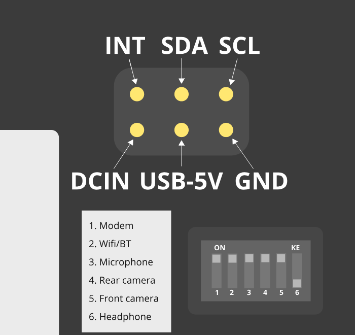
The pogo pins, as visible under the back cover.
The PinePhone has six pogo pins on the back allowing for custom hardware extensions such as wireless charging, an IR blaster, a keyboard extension or extended battery case. The pogo pins provide access to an interrupt line, power inputs/outputs and an I2C interface.
| Interrupt | SDA | SCL |
| DCIN | USB-5V | GND |
DCIN and USB-5V are the names used in the schematics. The actual behavior of these pogo pins is not obvious based on their names. DCIN is connected both to the VBUS line of the USB Type-C connector and to the ACIN/VBUS inputs on the PMIC. This means that, depending on a number of factors, DCIN may be at 0 V or 5 V. USB-5V is connected at the output of an LP6226 DC/DC boost converter (5 V), which in turn is fed by the PS output of the PMIC. The boost converter is enabled or disabled by a GPIO output from the A64 SoC, controlled by software (e.g. the Linux kernel). Depending on inputs and decision made by the PMIC, PS may be at the battery voltage (fed “directly” by the battery through a transistor controlled by the PMIC), or at the “USB” voltage (fed by the PMIC’s ACIN/VBUS inputs). This means that depending on a number of factors, USB-5V may be at battery voltage (between 3.0 V and 4.3 V), or at 5 V.
Because the PinePhone may act as a USB host (providing 5 V at the USB Type-C connector’s VBUS to a connected device) or as a USB device (drawing from a 5 V source on the USB Type-C connector’s VBUS), DCIN is actually not strictly an input nor an output. Some community analysis of the PinePhone schematic (and some testing) indicates that you can connect a 5 V power supply to DCIN in order to power the phone at the PMIC’s ACIN/VBUS inputs (and, as a side effect, charge the battery). This may not be safe to do in all conditions, e.g., when the phone is acting as a USB host to a connected USB device. It should also be safe to use DCIN as a power output from the PinePhone, e.g., when a USB Type-C charger is connected, you can draw current directly from the USB Type-C port’s VBUS, which is provided by the charger. Please note that, when using DCIN as an output from the PinePhone, DCIN isn’t “always on”; it may be 0 V. It is currently not documented on how much current can be safely drawn.
USB-5V should be safe to use as an “always on” power output from the PinePhone. Depending on a number of factors, voltage may be from 3 V to 5 V; thus, if you are using USB-5V to power your pogo-pins expansion board, you will probably need to use DC/DC converters/regulators as appropriate. USB-5V is on even while the A64 SoC is powered down.
The I2C and interrupt lines have pull-ups on the phone side. The I2C lines are pulled up to 3v3 by the phone.
For a breakout board see here. For an example project see Martijn’s blog post “Making a backcover extension for the PinePhone”.
PINE64 store currently sells the PinePhone Flex Breakout Board. With the pitch being 2.54 mm, this Flex Breakout Board may have leads soldered directly to the contacts for use in a solderless board. A non-soldered solution would be to use a TE AMP Connector that will accept a Flat Flexible Cable 2.54 mm pitch.
Back cover
A step file for the back cover for creating custom cases is freely available here.
Serial console

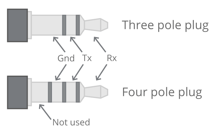
Pinout of the serial adapter.
The PinePhone has a serial port in the headphone connector, it’s activated by the 6th contact on the dipswitch. If the switch is set to “on”, the headphone connector is in audio mode, if it is set to “off” it’s in UART mode. The UART serial connection can also be used for communication with other devices from the PinePhone.
The UART is 115200n8.
The pinout for the serial connector is:
- Tip: RX
- Ring: TX
- Sleeve: GND
You can buy a serial debug cable from the PINE64 Store. The store cable uses a 4 ring plug, as seen in the here, but a 3 ring plug works just as well. The cable uses a CH340 chipset based serial to USB converter, but any 3.3v serial connection can be used. Because it is a “host”/DTE it means that you need a cross modem cable (Null Modem) with TX on Tip to be connected to RX. A cable like e.g. FTDI TTL-232R-3V3-AJ which has TX on Tip and RX on Ring fits perfectly.


