Project Anakin
The Project “Anakin” - Phase 1 of PINE64 Smartphone “PinePhone” Development Kit
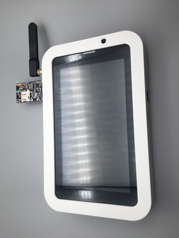
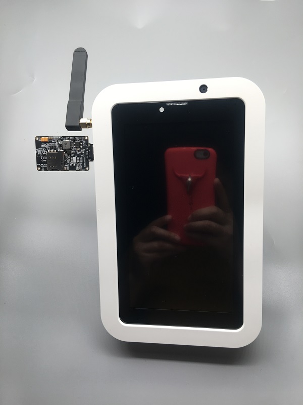
Project Anakin is a marsh-up kit for the PINE64 Smartphone dubbed “PinePhone”. It is used in the early stages of development as a starting point for affiliated projects.
PinePhone development has been broken down into three distinct phases:
- First phase - Project Anakin
- Second phase - purpose-built development kit code named “Don’t be evil”. It will be introduced at FOSDEM 2019
- Lastly, the third phase which is the PinePhone itself - scheduled to be released in Q3 2019 (pending on software development).
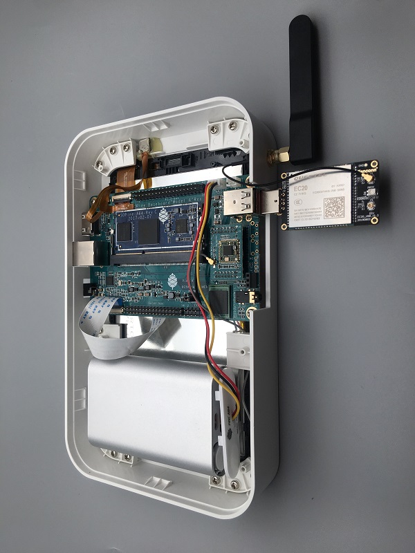
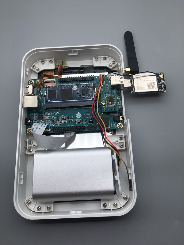
The Anakin kit consists of following components:
- SoPine Module
- SoPine Model A baseboard
- Pine A64 Wifi/BT module
- 16GB eMMC module
- 5 Mega Piixel CMOS Camera Sensor
- 7" Touch Screen LCD Panel
- Playbox Enclosure
- Lithium Ion Battery case (note: battery not included, can accommodate 1-3 pieces of 18650 size Lithium Ion batter. In general, one is good enough)
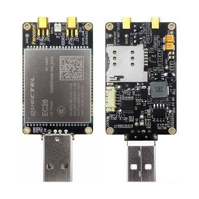
- Quectel EC20 R2.1 LTE Module (note: The SIM tray design not distinguish polarity well and all reverse slot in)
Accessories Step-by-Step Guides
Under ‘Guides for PINE A64(+) accessories’ you can find instructions and guides concerning:
- Playbox Enclosure
- Bluetooth and WiFi module
- 7" Touch Screen LCD Panel
SoC and Memory Specification
- Based on Allwinner A64/R18
- R18 and A64 are identical SoC but R18 committed for 10 years supply by vendor.
CPU Architecture
- Quad-core ARM Cortex-A53 Processor@1152Mhz
- A power-efficient ARM v8 architecture
- 64 and 32bit execution states for scalable high performance
- Support NEON Advanced SIMD (Single Instruction Multiple Data) instruction for acceleration of media and signal processing function
- Support Large Physical Address Extensions(LPAE)
- VFPv4 Floating Point Unit
- 32KB L1 Instruction cache and 32KB L1 Data cache
- 512KB L2 cache
GPU Architecture
- ARM Mali400MP2 Dual-core GPU
- Support OpenGL ES 2.0 and OpenVG 1.1 standard
System Memory
- RAM Memory Variants: 2GB LPDDR3.
- Storage Memory: SPI Flash and optional eMMC module from 16GB up to 64GB
Project Anakin, SOPine Module and Baseboard Information, Schematics, and Certifications
- Model “A” Baseoard Dimensions: 133mm x 80mm x 19mm
- Input Power: DC 5V @ 2A, 3.7V Li-Ion battery connector, 3.5OD/1.35ID Barrel DC Jack connector, Euler connector
- PINE A64 Connector Layout @courtesy of norm24
- PINE A64 Connector List
- SOPine Module Pin Assignment ver 1.0
- PINE A64 Pi-2/Eular/Ext Bus/Wifi Bus Connector Pin Assignment (Updated 15/Feb/2016)
- Good documentation about PINE A64, A64+, and A64-LTS GPIO pins article
SOPine Module Schematic:
SOPine Model “A” Baseboard Schematic and PCB Board Resource:
- SOPine model “A” Baseboard is an hardware open source project but is not “OSH” compliant
- SOPine Model “A” Baseboard Schematic capture Rev B DSN source file
- SOPine Model “A” Baseboard Schematic Rev B PDF file
- SOPine Model “A” Baseboard PCB Job source file
- SOPine Model “A” Baseboard PCB Gerber file
- SOPine Model “A” Baseboard PCB Layout PDF file
SOPine (together with model “A” baseboard) Certification:
- SOPine with model “A” baseboard FCC Certificate
- SOPine with model “A” baseboard CE Certificate
- SOPine with model “A” baseboard RoHS Certificate
Datasheets for Components and Peripherals
Allwinner A64/R18 SoC information:
- R18 and A64 are identical SoC but R18 committed for 10 years supply by vendor.
- Allwinner A64 SoC Brief Introduction
- Allwinner R18 SoC Brief Introduction
- Allwinner A64/R18 SoC Data Sheet V1.1 (Official Released Version)
- Allwinner A64/R18 SoC User Manual V1.0 (Official Release Version)
X-Powers AXP803 PMU (Power Management Unit) information:
LPDDR3 information:
eMMC information:
- PINE64 eMMC module schematic
- PINE64 USB adapter for eMMC module V2 schematic
- PINE64 USB adapter for eMMC module PCB in JPEG
- SanDisk eMMC Datasheet
- Hynix eMMC Datasheet
- Foresee eMMC Datasheet
SPI NOR Flash information:
Project Anakin module/component related information
5MPixel Rear CMOS Camera module information:
- PINE64 YL-PINE64-4EC 5M Pixel CMOS Image Sensor Module (Description in Chinese)
- S5K4EC 5MP CMOS Image Sensor SoC Module Datasheet
- S5K4EC 5MP CMOS Image Sensor SoC Chip Datasheet
- S5K4EC 5MP CMOS Image Sensor Driver Source Code in C language
LCD Touch Screen Panel information:
- 7.0" 1200x600 TFT-LCD Panel Specification
- Touch Panel Specification
- GOODiX GT911 5-Point Capacitive Touch Controller Datasheet
Ethernet PHY information:
- Realtek RTL8211 10/100/1000M Ethernet Transceiver for PINE A64+ Board
- Realtek RTL8201 10/100M Ethernet Transceiver for PINE A64 Board
Wifi/BT module information:
Enclosure information:
Connector information:
- 2.0mm PH Type connector specification use in Lithium Battery (VBAT) port and RTC Battery port
- 0.5mm Pitch cover type FPC connector specification use in DSI port, TP port and CSI port
right
LTE module information:
- Note: The current Project Anakin kit deploy on using Quectel EC20_R2.1 which belongs to EC25 family. Actual production will use EC25 and EG25-G (still preliminary) module pending on region.
- Quectel EC20 R2.1 LTE Module Specification
- Quectel EC25 LTE Module Specification
- Quectel EG25-G LTE Module Specification
- Quectel EC25 LTE Module AT Cammands Set Manual
- Quectel EC25 LTE Module Hardware Design Guide
- Quectel EC25 LTE Module Reference Design Guide


