PinePhone (Single Page)
The PinePhone is a smartphone created by PINE64. It is capable of running mainline Linux and is supported by many partner projects.
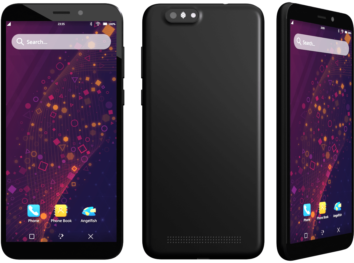
The Braveheart Edition of the PinePhone was the first publicly available version of the phone. It shipped without a fully functional operating system and was geared specifically towards early adopters. The Braveheart Edition’s successors were the Community Editions, which featured a branded backcover and box of selected community projects. The Community Editions became available in June 2020. The Beta Edition featuring Manjaro with Plasma Mobile is the latest edition, it became available in March 2021.
Introduction
The PinePhone is not a regular phone and you might not get the latest and greatest hardware and this years’ newest innovation. You will get a device with good mainline support with a great community behind it.
State of the software
First things first, the PinePhone is aimed solely at early adopters - more specifically, the units are solely intended to find their way into the hands of users with extensive operating system experience.
Bear in mind that the software for these smartphones is very early, with most of the software being in alpha or beta state. That’s especially also the case for scalability of applications, their availability and practicability, any hardware function implementations and the firmware. The software is provided as is. There is no warranty for the software, not even for merchantability or fitness for a particular purpose.
If you have any questions regarding the current state of the software or of specific features working, please don’t hesitate to ask in the community chat (see Main Page)!
Help and support
Still have any questions regarding software, shipping, or ordering after reading this wiki? Please don’t hesitate to contact the community in the bridged community channels for detailed answers or simply to chat with friendly people in the community! See Main Page.
Please keep in mind that PINE64 is not like a regular company (see the PINE64 philosophy) and that support resources are limited - the best way to get support quickly is to ask in the community chat! Please only contact the PINE64 support directly if questions couldn’t be solved via the community chat or this wiki.
Getting started
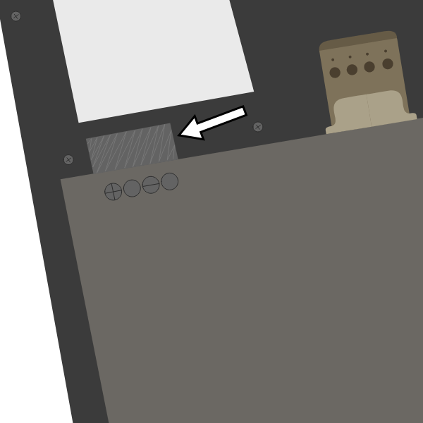
A protection foil isolates the battery for the shipping.
When shipped the battery is isolated from the device using a protective plastic tab, which is required to be removed before using the phone. The battery will not charge or boot until it is removed and the battery is connected again.
The PinePhone’s SIM slot only accepts a micro-SIM, please do not insert a nano-SIM without an adapter and make sure that the nano-SIM does not get released from its adapter. The SIM card has to be placed in the lower slot, while the microSD has to be placed in the upper slot.
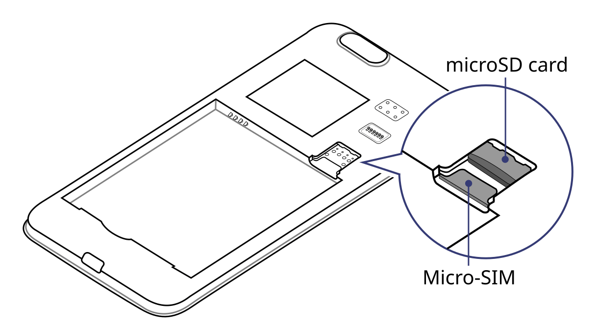
The microSD belongs in the upper slot, the micro-SIM in the lower slot.
An adapter from a nano to a micro-SIM might be included under tape in the camera notch of the phone’s packaging. Some nano-SIMs will not fit firmly into that adapter that comes with the PinePhone and if the included adapter is used without a well-fitting nano-SIM, the contact pins might get damaged. In that case it is highly recommended to acquire a better fitting adapter.
Installation
To learn more about the boot priority on the PinePhone, click on boot priority.
The installation instructions can be found here:
The releases for the PinePhone can be found under Releases.
Boot priority
The PinePhone always boots from the microSD card first. It is therefore recommended to have a microSD card handy. It is not possible to lock themself out of the phone when the installation on the internal storage (the eMMC) fails, as a correctly flashed microSD card will always boot. Note: Booting from USB is not supported by the hardware, a live USB stick will not boot.
The phone will also try to boot from microSD cards, which were previously flashed with an OS and formatted later, causing the phone to fail to boot. See reuse microSD card on how to format the microSD card properly, including wiping the residues of u-boot.
Installation to the microSD card
For this installation method you need a microSD card, a microSD card reader and a compatible device, such as a computer or a laptop with Linux, iOS, Windows or similar (note: ChromeOS is not supported).
To install an image to the microSD card:
- Download your chosen image from Releases for the regular PinePhone (not compatible with the PinePhone Pro).
- Extract the compressed file
- Write (flash) the image to your microSD card, see the instructions below
- Plug microSD card into phone (make sure to use the top slot, not the bottom slot)
- Boot up the phone

The microSD belongs in the upper slot, the micro-SIM in the lower slot.
Using Balena Etcher
Using the graphical application Balena Etcher to flash the microSD card is ‘recommended’ for new or inexperienced users.
Download and install the application: https://etcher.balena.io/#download-etcher
Then start it and click the button Flash from file:
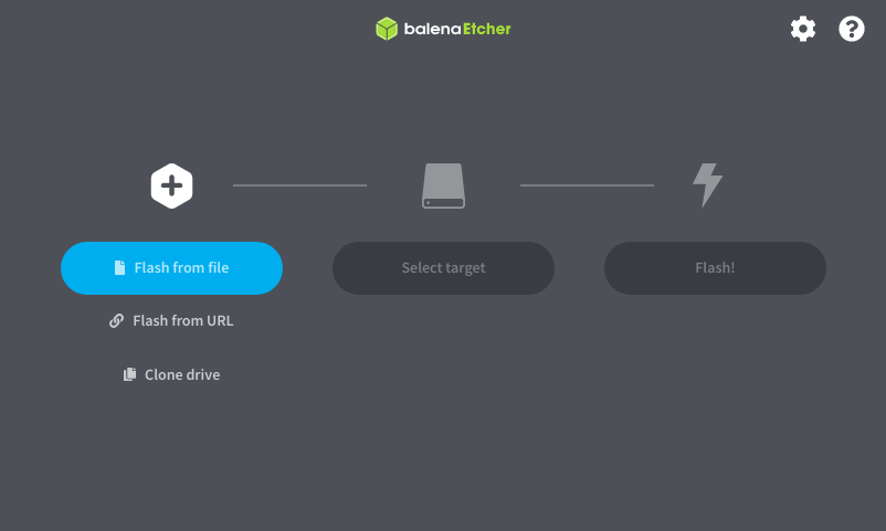
Select the downloaded image and make sure that you downloaded the correct one. Images for the PinePhone and the PinePhone Pro are ’not compatible’ with each other. Images for the PinePhone typically have the word “PinePhone” in the filename, while images for the PinePhone Pro typically have “PinePhone Pro” in their filename.
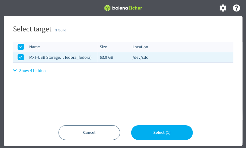
Then click on Select target:
Then click on Flash!:
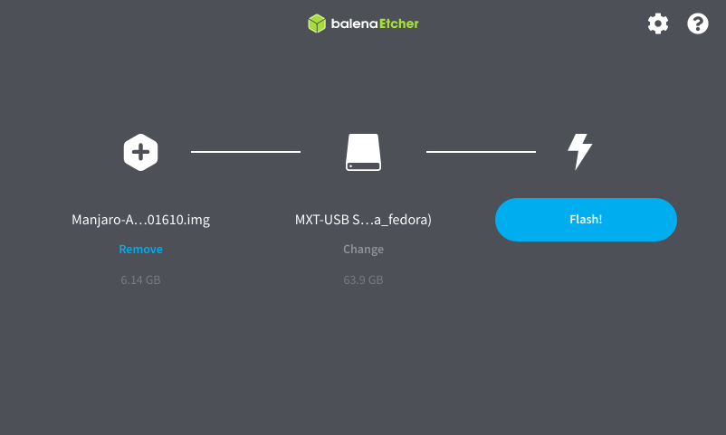
That’s it!
Using dd
For flashing the microSD card, the command dd can be used as well.
Make sure to select the correct device using lsblk. Then run dd with the selected device:
sudo dd if=IMAGE.img of=/dev/[DEVICE] bs=1M status=progress conv=fsync
Using bmaptool
Make sure to select the correct device using lsblk. Then run bmaptool with the correct device:
Download the IMAGE.xz and the IMAGE.bmap files, then run:
bmaptool copy --bmap IMAGE.bmap IMAGE.xz /dev/[DEVICE]
This takes around 2.5 minutes to flash a 4 Gb file.
Using Gnome Disks
The graphical application Gnome Disks can be used to flash the microSD card as well.
To do so, select the correct device in the left device selection, then click on the three dot menu and select Restore Disk Image… and follow the on-screen instructions.
Installation to the eMMC
The internal memory of the PinePhone (eMMC) can be flashed using multiple different methods.
From the booted microSD OS
- Flash an OS to the microSD card (and optionally resize the partition, see below)
- Insert microSD card and boot the phone
- Download the desired OS’ image on the booted OS or transfer it to the microSD card
- Extract the image file if it is archived
- Flash the image file to eMMC using
dd if=IMAGE.img of=/dev/mmcblkX bs=1M conv=fsyncwhere X is the number label of the eMMC (of the disk, not the partition!). Use the commandlsblkto check your devices: typically with the current kernel the microSD card is /dev/mmcblk0 and the eMMC is /dev/mmcblk2 but as always with dd be extremely cautious to get the devices correct. - Turn off phone, remove microSD card and then turn on the phone.
Using JumpDrive
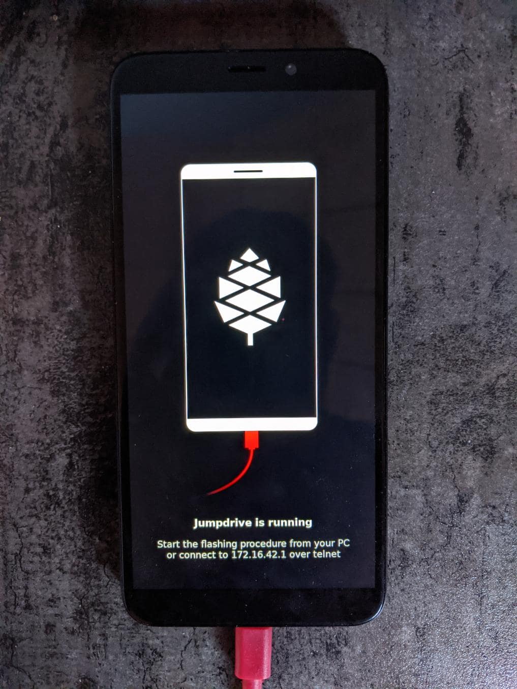
Jumpdrive running on the PinePhone
The internal eMMC flash storage can be flashed using the Jumpdrive utility by Danct12 and Martijn from postmarketOS. This utility boots from micro SD and exposes the internal eMMC flash storage when the PinePhone is connected to a computer. The process of flashing an OS to the exposed and mounted eMMC is identical to that of any other storage medium - e.g. a microSD card. You can use the dd command or a utility such as Etcher or Gnome Disks, etc.
Latest Jumpdrive can be found here.
- Download and extract the Jumpdrive image
- Flash the Jumpdrive image to a microSD card
- Boot the PinePhone from the Jumpdrive microSD card
- Connect the PinePhone to your computer using USB-A -> USB-C cable
- Flash the exposed PinePhone drive (e.g. /dev/mm…, check for the right device in
dmesg, GNOME disks, or similar, and make sure it’s unmounted) with your chosen OS image - Once the flashing process is complete, disconnect the PinePhone from your PC, power it down and remove the Jumpdrive microSD card
- The process is now finished, and you can boot from eMMC
The Jumpdrive image is smaller than 50MB. You can keep an microSD card specifically for using Jumpdrive, and there are 64MB microSD cards sold cheaply that will suffice. Jumpdrive also acts as a rescue image in case if you messed up your installation. To do so, you can telnet to 172.16.42.1, mount rootfs and fix it!
SD to eMMC via installer
An special installer image booted from the microSD card can be used to flash the eMMC as well. Mobian and postmarketOS installer images booted from microSD card will simply ask the user if they want to install to eMMC. The feature lives in the distribution-agnostic calamares-extensions repository (see calamares-extensions#7), so other distributions might adopt this in the future.
Using Tow-Boot
Tow-Boot is an opinionated distribution of the U-Boot bootloader. It includes an USB Mass Storage Mode, which exposes the flash drive(s) to a computer connected to the phone via USB-C. The Tow-Boot bootloader has to be installed if it is not pre-installed already. For instructions see the following links:
- PinePhone: https://tow-boot.org/devices/pine64-pinephoneA64.html
- PinePhone Pro: https://tow-boot.org/devices/pine64-pinephonePro.html
If Tow-Boot is installed the phone can be started into USB Mass Storage Mode by holding the volume up key on startup.
The steps of flashing an operating system to the phone after booting Tow-Boot’s USB Mass Storage Mode and connecting the phone to a computer is identical to that of any other storage medium - e.g. a microSD card. You can use the dd command or a utility such as Etcher or Gnome Disks from the computer the phone is connected to.
Reuse microSD card
Once you have installed your release of choice to eMMC, you may wish to use an microSD card for data storage. If you choose to re-use a card you have previously used to boot from, you will find your phone might not boot if you just reformat the card and insert it. This is because the Allwinner firmware in the PinePhone uses some (normally) unused space at the front of the microSD card to store boot software, which you need to clear.
This can be done as follows on any Linux system:
lsblk
to check the device of your microSD card – as an example lets assume it is /dev/mmcblk0 then
sudo dd if=/dev/zero of=/dev/[DEVICE] bs=8k seek=1 count=4
will clear the relevant sectors of your card.
Since Danctnix (arch) switched to a gpt partition table from mbr in May of 2022 it installs u-boot at an offset of 128k instead of 8k, which means this command must be used instead
sudo dd if=/dev/zero of=/dev/[DEVICE] bs=32k seek=4 count=1
Extend partition
Once you’ve flashed the OS to your microSD card or eMMC storage, you may also need to expand the partition to fill all the available space.
Resize SD card’s partition using computer
For microSD cards, insert the microSD card and resize the partitions through the computer. For eMMC, insert the phone cable and use Jumpdrive to access the eMMC directly, and resize the partition after flashing the image. To do the flashing you have two options:
Using Growpart
Install growpart and run:
growpart /dev/**mmcblkX** **Y**
resize2fs /dev/**mmcblkXpY**
where X is the storage device and Y is the partition number (viewable from lsblk).
If you get any errors about missing or unknown commands, use apt-cache search to find and install the needed software. Also don’t forget to use sudo.
Using Parted
Parted’s interactive mode and resize work well together. Do this before you put your microSD card into the PinePhone for the first time for best results.
sudo parted /dev/*<your_sd_card_device>*
(parted) resizepart 2 100%
(parted) quit
sudo resize2fs /dev/*<the_second_sd_card_PARTITION>*
Resize from within the PinePhone
eMMC: you would need to resize the partition on eMMC (flashed with the operating system) by booting another image from the microSD card: that way, the eMMC will be unmounted. It is not recommended to resize eMMC while booted from eMMC! Resizing a currently mounted partition can have weird results. If you booted from the microSD card, you can follow the above guidelines on how to resize from a computer.
MicroSD card: It is generally not possible to boot from eMMC to partition the unmounted microSD card, because of the boot order - you would have to write the image to the empty microSD card first, then resize partition, all without rebooting. It is also not recommended to resize the microSD card while booted from microSD card! Resizing a currently mounted partition can have weird results.
Releases
This page provides a comprehensive and alphabetically organized list of available software releases and tools for the PinePhone. For guidance on installing the operating systems, please refer to the Installation instructions.
Software Releases
Arch Linux ARM

(Unofficial) Arch Linux ARM with choice of Phosh UI, Plasma Mobile, sxmo or barebones.
It is maintained by the DanctNIX community (GitHub: danctnix, dreemurrs-embedded).
Download
Get both stable and test builds at GitHub releases.
| Default credentials | |
|---|---|
| Default user | alarm/123456 |
| root (barebone only) | root/root |
Notes
- There are archmobile chat rooms on Matrix (#archmobile:kde.org) and Telegram (@archmobile).
- Feel free to send us pull requests and reports issues on GitHub.
Fedora

An (unofficial) vanilla Fedora rawhide build for aarch64 with megi’s kernel and some additional packages to tie it all together. It aims to eventually be an upstream part of the Fedora project, rather than a phone-specific distribution.
- Forum discussion: Fedora + Phosh for PinePhone
- GitLab: Fedora Mobility SIG
Download
There is also an FTP server with images build every night @ ftp://pine.warpspeed.dk/nightly/pinephone/ (Mount this with something like Nautilus)
| Default credentials | |
|---|---|
| Nightly images (via FTP) | pine/1111 |
Notes
WiFi, Bluetooth, SMS, Data, Calls all work|There are still a few bugs though, and some features don’t have driver support yet on any PinePhone distribution.
Please send your bug reports to the project’s issue tracker. Be sure to include logs if applicable|Send us pull requests on GitLab.
Gentoo

There are unofficial Gentoo overlays with ebuilds for the PinePhone. There are no images - the image must be built manually, including picking the kernel, bootloader and the desired desktop environment. The ARM64 version of Gentoo has to be selected.
Download
Overlay locations:
Notes
The documentation can be found here:
- https://blog.gjdwebserver.nl/ords/f?p=107:HOME:::::ARTICLE:gentoo-on-a-pinephone
- https://blog.gjdwebserver.nl/ords/f?p=107:HOME:::::ARTICLE:gentoo-on-a-pinephone-making-it-a-usable-phone
- https://blog.gjdwebserver.nl/ords/f?p=107:HOME:::::ARTICLE:gentoo-on-a-pinephone-pro
- https://wiki.gentoo.org/wiki/User:Dr41nU/PinePhone
- https://wiki.gentoo.org/wiki/PinePhone (incomplete)
GloDroid
A fully open-source port of Android and LineageOS to the PinePhone.
GitHub: GloDroid
Download
- Releases: GloDroid
Notes
Feature overview:
- Works: WiFi, screen dimming, sound, touchscreen, charging and telephony(partially) works.
- Doesn’t work: Bluetooth and GPS
- See more at project status page
Kali Linux

The official Kali Nethunter images for PinePhone and PinePhone Pro have been released now. For older/unofficial releases, you can still download from the GitHub releases page. Get Nethunter App for your PinePhone’s Kali Linux. Packet Injection is working now, use iwconfig instead of airmon-ng.
Download
| Default credentials | |
|---|---|
| Default user for Unofficial Releases | kali/8888 |
| Default user for Nethunter Releases | kali/1234 |
LuneOS

LuneOS is one of the original multi-tasking OS-es that runs on Linux. Based on HP/Palm’s webOS, merged with latest technology stack from LG called webOS OSE (a derivative of what LG uses on their Smart TV’s), software such as Qt5 and makes use of the Yocto build system.
- WebOS Ports Wiki
- GitHub: WebOS Ports
Download
- Release images: Releases
- Testing images: Open the testing releases page, then use Ctrl + F to search release that built image for PinePhone
| Default credentials | |
|---|---|
| Default user | root |
Notes
In order to connect to the device using SSH/SCP via WiFi: You can simply connect via SSH/SCP via WiFi using the PinePhone’s IP address on port 22.
Maemo Leste

Maemo is a trimmed-down version of Debian for mobile devices, originally a collaboration between Nokia and many open source projects (the Maemo community) before Nokia abandoned it. The more well-known devices Maemo supports are the OpenMoko and N900. The community now takes full responsibility in developing fully open source Maemo for a variety of mobile devices. You may be interested to learn more about the features in their Maemo Leste FAQ.
Maemo 8 “Leste” is an ARM64 port of Devuan (Debian without systemd) and runs the mainline Linux kernel. The default user interface stack is Hildon, Xorg, Matchbox WM, and GTK.
Download
There is also an image builder, see the wiki for instructions on how to build a custom image. For current status and instructions, please read their PinePhone wiki page.
| Default credentials | |
|---|---|
| root | toor |
| user | 12345 (lockscreen) |
Notes
Most discussion occurs at #maemo-leste on irc.libera.chat (link) and this thread.
All other contact information is listed on the main page of the Maemo wiki.
Submit bug reports on GitHub. To track known issues, you may use these search terms: pinephone and pine64.
Manjaro ARM

Manjaro is a user-friendly Linux distribution based on the independently developed Arch operating system with the Plasma Mobile and Phosh desktop environment.
Download
| Default credentials (Only Phosh) | |
|---|---|
| Default user | manjaro/123456 |
| root | root/root |
Notes
The installation of the stable images is strongly suggested. The dev images might break frequently.
Mobian

A Mobian build for ARM64 running with Phosh (developed by Purism, uses Wayland instead of Xorg). The current version of the base Debian system is Debian Bookworm. Only the GUI applications and a few others (ModemManager, WiFi chip firmware) are built from modified sources (as well as the kernel and u-boot).
Download
| Default credentials | |
|---|---|
| Default user | mobian/1234 |
Notes
The development is work in progress. See pinephone-support for further information. The Mobian wiki can be found here.
In order to connect to the device using SSH/SCP via WiFi, you need to install SSH on the device. You can do this by executing the following in a shell: “sudo apt-get install ssh”, afterwards you can connect via SSH/SCP via WiFi using the PinePhone’s IP address on port 22.
Movuan

Movuan is the incipient stage of a new distribution for the PinePhone. It is derived from Mobian, yet using Devuan instead of Debian. The image attempts to be as short lived as possible, hoping to get merged into mainline Devuan as soon as possible.
Download
This is a split zip file. To extract it, the following command can be used:
7z e movuan-pinephone-phosh-daedalus-20250224.img-split.zip
| Default credentials | |
|---|---|
| Default user | movuan/1234 |
Notes
- Current image version is based on Devuan Daedalus.
- Source Code
- Announcement/Discussion/Motivation
- Further interest Customizing Movuan under Host Mounting
At this time expecting feedback or offers to help with building/packing.
Anybody is welcome to fork this project, or use it in any GPL compliant way. Use a different name though and change the logo, and notify the author of the project to review if it can be incorporated back.
If you want to just mirror the code and provide additional pre-built images on a different server, there is no need to change the logo/name. Just make sure to prominently point to the original location.
Multi-distro demo image
This image allow users to try many Linux distributions easily, without having to figure out how to flash them individually and juggle with many microSD cards. Also called megi’s 15-in-1 multi boot image.
- Main page: https://xnux.eu/p-boot-demo/
- Git repo: https://megous.com/git/pinephone-multi-boot/
- Forum discussion: 15-distro multi-boot image for Pinephone
Download
Update 2022-01-26, using megi’s kernel 5.16.2
DD image to SD card and boot. This image is for 16GiB or larger SD cards, also works if flashed to eMMC.
This is also a good build for charging depleted battery. Just boot up this build with power supply connected, keep the PinePhone charging for 3 hours at power down stage.
For more info on this build, please visit its entry the “News” section of its web page.
- Download torrent file from author’s website
- File name: multi.img.zst
- SHA-256: 39915b9d2aa2f33fd78552ac9a0e665c4aef97dd68a9f9a6c76f9fa2f0ac049e
- File Size: 6.9GiB
Due to its size, download though torrent is suggested by the author on its main page.
| Default credentials | |
|---|---|
| General | 1111 |
| sxmo | user/1111 |
| Manjaro | seems to insist on 123456 |
Notes
Note about zstd archive file (.zst):
On Linux, you may install or compile zstd, then write the image to SD card by piping zstdcat and dd. See the “Installation” section of its web page for command examples.
On Windows, instead of the offical zstd command line program, you may use 7-zip-zstd. Different installation method is provided in their README. Install 7-Zip-zstd / zstd, extract the disk image file (.img) from the zstd archive, and flash with tools like Win32 Disk Imager.
Also see Installation instructions.
Nemo Mobile

Nemo Mobile is an open source build of Sailfish OS with a open source UI called Glacier, based on Manjaro.
- NemoMobile Website
- Installation Guide for both real devices and Virtualbox
Download
- Latest release, not every device are built every time.
- Older release:
yyyy.mm/dirs under https://img.nemomobile.net/. Has every supported device’s image. Themanjaro/dir only contains the software packages instead of installation images.
| Default credentials | |
|---|---|
| Default user | manjaro/123456 |
| root | root/root |
Notes
Please report bugs regarding the Nemo Mobile UI as GitHub issue. Checkout the troubleshooting and contributing guide to learn more.
NixOS

NixOS is a Linux distribution built on top of the Nix package manager using declarative configuration to allow reliable system upgrades.
Download
There is a guided installer by the Mobile NixOS project available. An installer image that can be flashed to a sdcard can be downloaded from the Hydra build instance.
Users that want to build a local image, are expected to follow the instructions in the Getting Started page, and Project’s device page.
Notes
Project home page: Mobile NixOS
OpenMandriva Lx 4.2 RC

OpenMandriva Lx 4.2 RC with Plasma Mobile as UI. The development ceases before a newer release is out.
Download
The official image can be found at sourceforge.net. See here for the offical announcement.
Notes
openSUSE

Our images use the same openSUSE Tumbleweed base as our desktop images, except what needs to be changed for the PinePhone. The images include zypper (RPM) as the default package manager, and have access to virtually the same (open source) software as our desktop repositories, thanks to the Factory ports. Using dnf is possible, if preferred.
Download
To verify the images you need to import our GPG key. Keep on mind that the first boot may stay on black screen for about a minute - consequent boots should be faster.
You can find install instructions at this section in the openSUSE Wiki.
| Default credentials | |
|---|---|
| Default user | pine/1234 |
| root | root/linux |
Notes
You can find all information about the releases of the project here. Detailed information, tips and troubleshooting suggestions are also provided at the openSUSE Wiki. You will also find information in our wiki on how to report issues (Contributing section).
postmarketOS

postmarketOS extends Alpine Linux to run on smartphones and other mobile devices. It offers various user interfaces (Phosh, Plasma Mobile, Sxmo, Plasma Desktop, Gnome 3, Kodi, XFCE4 and others).
Download
| Default credentials | |
|---|---|
| Test images user | user/147147 |
Notes
As of writing, official images are provided with Phosh, Plasma Mobile and Sxmo. The official images come in two flavors, either as a test image to try out postmarketOS, or with the installer.
When using the installer images (recommended), it is possible to:
- encrypt the installation
- install from the SD card to eMMC
Power users may also create their own image with the distribution’s install and development tool pmbootstrap.
See the pine64-pinephone page of the postmarketOS wiki for details.
Rhino Linux
Rhino Linux is an Ubuntu-based distribution that uses the rolling-release model by tracking the devel` branch of repositories. The port is currently maintained by Oren Klopfer (oklopfer).
Tow-Boot is required for installing Rhino Linux. Instructions for installing Tow-Boot to the PinePhone can be found here. After Tow-Boot has been installed to your device, Rhino Linux installation just requires flashing the .img.xz to an SD or the eMMC.
Download
Rhino Linux Downloads (select Pine64 on the dropdown)
| Default credentials | |
|---|---|
| Default user | rhino/1234 |
Notes
Foundational to the distribution is Pacstall, a Debian-based user repository inspired by the AUR. Additionally, RL comes with Unicorn, a custom modified version of XFCE with various modernizations and improvements, including auto-rotation for mobile devices.
Discord - Matrix - GitHub - Wiki
Sailfish OS

Sailfish OS is a Linux-based operating system based on open source projects such as Mer, and a closed source UI based on Lipstick.
- PinePhone Wiki Page on Mer Wiki, for both Nemo Mobile and Sailfish OS.
- Linux kernel config repo
- Sailfish OS repo
Download
Flashing script
The Sailfish OS image is built on Gitlab CI. The latest image can be installed using the flashing script.
The script downloads the image and bootloader from the CI, extracts everything and burns it onto the SD card.
Instructions:
- Download the flashing script
- Insert a microSD card in your device
- Make the script executable:
chmod +x flash-it.sh - Verify that you have the
bsdtarpackage installed - Execute it:
./flash-it.sh - Follow the instructions. Some commands in the script require root permissions (for example: mounting and flashing the SD card).
When asked where to flash, type ‘raw’ and it will build the image on your computer. Otherwise define the path /dev/[…]. to flash to card or internal emmc.
username/password
Set PIN on initialization.
Notes
- Sometimes the first run stalls before the tutorial. Reboot and it will start from setting the security pin.
- The homescreen may be locked unless you boot with a sim card inserted. An old expired sim will do. If you do not have a SIM card on hands, do NOT set a security code on first boot.
- When a screen with a loading circle is displayed, just left/right swipe it away.
- If you’re not familiar with Sailfish OS, pay attention to the tutorial - the interface works great, but is not immediately obvious. If you are familiar with it, you can skip the tutorial by touching all 4 corners starting top left.
What works, what does not work
See the Hardware Support section on the Mer Wiki’s PinePhone Page.
There is a limited selection of apps available from the Jolla store, the vast majority are hosted on openrepos.net. If the Storeman app for openrepos is not preinstalled, download the RPM and click to install.
How to contribute and report defects
See the documentation wiki at the github project for help and links.
See the Installation section on the Mer Wiki’s PinePhone Page for compile, build and development.
Git repo links are at the top of this OS section. other repos that may be helpful:
- GitHub project page
- the repo of the flash-it.sh flashing script
- Mer Open Build Service page (Mer is being assimilated into Sailfish OS and OBS is shutting down, also see OpenStack is replacing OBS with another build system based on Jenkins, if it’s related, even OBS come back under Sailfish OS, it will be different.)
See the Sailfish OS wiki for links to their forum, as well as info required when reporting an issue. See the Sailfish OS wiki main page for options to contribute to Sailfish OS.
Notes
OTA is supported: zypper refresh && zypper update as root (devel-su to get root access). Things that need reflash are bootloader specific at the moment. If improvements like Crust or changes of partition layout are added, then you need to reflash.
SkiffOS

Minimal in-memory cross-compiled OS optimized for hosting multiple in parallel Docker containers. Provides the reliability of firmware with the ease-of-use of package managers.
Download
The repository and instructions can be found here.
Notes
Upgrade over-the-air via a simple rsync script, or copying 3 files.
Uses the Buildroot cross-compilation tool for support for all Pine64 boards.
Use configuration packages to configure distro:
| Package | Distro |
|---|---|
| core/pinephone_neon | KDE Neon via Ubuntu repositories |
| core/pinephone_nixos | Nixos Mobile |
| core/pinephone_gentoo | Gentoo with Link-time Optimization & KDE Mobile or Phosh |
| core/pinephone_ubports | Ubuntu Ports for PinePhone |
| core/pinephone_manjaro_kde | Manjaro for PinePhone: KDE variant |
| core/pinephone_manjaro_phosh | Manjaro for PinePhone: Phosh variant |
| core/pinephone_manjaro_lomiri | Manjaro for PinePhone: Lomiri variant |
The boot-up OS is upgraded independently from the containers.
Slackware
Slackware is the world’s oldest actively developed Linux distribution, providing a modern user land (applications) and Linux Kernel, within a more classic Unix Operating System environment.
Download
Notes
Discussion: Thread
Ubuntu Touch

A Mobile Version of the Ubuntu Operating System made and maintained by the UBports Community. The port is currently maintained by Oren Klopfer (oklopfer).
Installation instructions can be found at this UBports post. After Tow-Boot has been installed to your device, Ubuntu Touch installation just requires flashing the .img.xz to an SD or the eMMC.
Download
| Default credentials | |
|---|---|
| Default user | Set during boot |
| root | phablet/1234 |
Notes
Scroll down to the middle of the GitLab project page, or directly here at the UBports website to see which features work.
Contributions and bug reports can be made at the UBports PinePhone GitLab page. See UBports website for how to donate.
Tools
There are software tools, that can be booted on the PinePhone.
JumpDrive
JumpDrive can be used to flash the eMMC (and the microSD card), see Installation instructions.
See https://github.com/dreemurrs-embedded/Jumpdrive/releases for the latest image. Make sure to download the “PinePhone” image and to unpack the archive before flashing.
Tow-Boot
Tow-Boot is a more user-friendly distribution of U-Boot. It can mount internal storage as USB Mass Storage by holding the volume up button at startup before and during the second vibration. The LED will turn blue if done successfully.
See https://github.com/Tow-Boot/Tow-Boot/releases for the latest image.
Make sure to download the image with pinephoneA64 in the name.
Hardware test build
On the Braveheart model, there was a postmarketOS based basic Factory Test OS pre-installed on the eMMC. The developer Martijn Braam from postmarketOS has improved the functionality of the image considerably later. Since the 20200501 version, it is able to test all the hardware. It also includes functionality to install a new OS to the eMMC when using with an test image that includes that OS image. The downloadable image just does the hardware tests. Do not flash eMMC to test your device, just flash it to microSD and test from there. New versions are distributed as part of the postmarketOS distribution.
Links:
- Software Images (NOTE: Link is is broken) (download the latest one named like pine-pinephone-yyyyMMdd-factorytestX.img.xz)
- Git repo
- Documentation
Historic factory builds
These are different operating system builds that was preloaded in the factory with testing utility.
Download the build, extract the image and dd it to a 8 GB or larger microSD card, then insert it into the PinePhone. After power up or reboot, you may perform and complete the test routine, or apply the build from microSD card to eMMC.
All the download links below are direct download from pine64.org.
| Distribution | Download Link | File Size | MD5 |
|---|---|---|---|
| Beta Edition | pine64-pinephone-plamo-beta-factorytest.img.xz | 1.78GB | f16bce93504a52217540ac886863a418 |
| Mobian | pine64-pinephone-20201207-factorytest-mobian.img.xz | 1.41GB | 015be381ff4e650a7fca6d4eaa90d63d |
| KDE | pine64-pinephone-20201208-factorytest-kde.img.xz | 2.28GB | 32979ff17b5ec4d358ce99f1aff0c77c |
| Manjaro | pine64-pinephone-20201013-manjaro-stable-20201018-factory56.img.xz | 1.04GB | 4edfd4dceaefdd32a3417c1727161c29 |
| postmarketOS | pine64-pinephone-20200726-phosh-v20.05-factory.img.xz | 517MB | 244093be2f6d728fcbd1d29114607727 |
| Ubuntu Touch | PinePhone-flasher-ubuntu-7b.img.gz | 1.05GB | 2d7f5271e7a281db8f1b1219bedbe131 |
Further Releases
Apache NuttX RTOS
Apache NuttX RTOS is a Real-Time Operating System that supports PinePhone.
Sculpt Operating System (Genode OS Framework)
Sculpt OS since version 23.04 supports PinePhone.
Ready-to-use system image available on the download page.
Installing other ARM64 distributions
Other ARM64 distributions might be installed as well, however this requires some tinkering and may not work well.
General steps:
- Create a boot partition (from 4 MB to about 252 MB) and a root partition (from the end of boot to the end of the card) filesystem on the SD card.
- Format the boot partition with vfat, and the root partition with a supported filesystem like ext4 or f2fs.
- Extract the root filesystem from your distribution’s ARM image into the root filesystem on the SD card. Do not copy the partition, copy the files instead (in archive mode, like
rsync -ar). - Edit
/etc/fstabto match your partitions. - Grab megi’s kernel from https://xff.cz/kernels/, Follow the instructions in the README, which involves copying the kernel modules into the SD card rootfs, and writing u-boot and the bootloader.
If you would like to see examples or specific commands for how to complete these steps, see:
- an example for Fedora, current unofficial [#Fedora] release
- an example for Arch Linux by megi
Other Resources
Other software information
- sunxi community wiki
- megi’s feature/driver support matrix
- megi bootUI notes (for dualbooting/multibooting) see demonstration on YouTube
- ayufan boot tools
Other
- Pine64 blog on blobs
- Martijn Braam Librem 5 comparison, especially covering openness/blobs
- Bart Ribbers blog on Linux distributions and desktop environments on mobile devices
- Jeff Geerling on testing microSD cards
Troubleshooting
If the PinePhone is not booting from eMMC and/or microSD card anymore it can have two causes:
The battery is drained
If the battery is fully drained, most operating systems and distributions won’t boot anymore. One of the exceptions which still boots is the utility Jumpdrive, which can usually be used to expose the eMMC and microSD card as drives to a USB-connected computer. Mind that JumpDrive won’t expose the eMMC and microSD card with a drained battery but it still can be flashed and booted from microSD card to confirm that the phone still functions and boots up fine.
JumpDrive can be downloaded from here (not compatible with the PinePhone Pro!).
Alternatively to testing JumpDrive, the issue can also be diagnosed by checking the battery charge. Simply remove the battery from the device and measure the voltage on the (+) and (-) contacts on the battery. Make sure to not shorten the contacts as shorting battery pins is a severe life and safety danger.
The installation is corrupted or incorrect
If the installation of the prioritized boot medium is corrupted or incorrect, the PinePhone will not boot anymore. The following problems are common:
- The microSD card is in the wrong slot (see first time installation)
- The image file was flashed to partition 1 (example: sdx1, nvme0x1p1) instead of the whole device (example: sdx, nvme0x1)
- An image without bootloader was flashed (mind the Tow-Boot bootloader requirements of Mobian and postmarketOS)
- The operating systems got corrupted, for example after running updates (reflash the device, see Installation instructions)
- An incompatible image was flashed (make sure that the images are compatible. Images for the PinePhone Pro won’t boot on the PinePhone and vice versa. Check your invoice to see if you ordered a PinePhone or a PinePhone Pro).
Modem
The PinePhone uses Quectel EG25-G as modem. AT commands are used to communicate with the modem.
AT commands
A list of documented AT commands can be found for example in this AT commands documentation from Quectel. Further undocumented AT commands found by the developer megi, who reverse-engineered parts of the modem and its firmware, can be found on megi’s website here.
To send AT commands to the modem under Linux, minicom or the often-preinstalled atinout utility can be used.
atinout example:
echo "AT+<command here>" | sudo atinout - /dev/ttyUSB2 -
minicom example:
minicom -D /dev/ttyUSB2
VoLTE
The PinePhone’s modem supports VoLTE and comes with a few VoLTE profiles preloaded. Most operating systems try to set the correct profile automatically.
To list the available VoLTE profiles:
AT+QMBNCFG="list"

+QMBNCFG: "List",0,1,1,"ROW_Generic_3GPP",0x0501081F,201901141
+QMBNCFG: "List",1,0,0,"VoLTE-ATT",0x0501033C,201909271
+QMBNCFG: "List",2,0,0,"hVoLTE-Verizon",0x05010141,201911251
+QMBNCFG: "List",3,0,0,"Sprint-VoLTE",0x05010205,201908141
+QMBNCFG: "List",4,0,0,"Commercial-TMO_VoLTE",0x05010505,201811231
+QMBNCFG: "List",5,0,0,"Telus-Commercial_VoLTE",0x05800C43,201912031
+QMBNCFG: "List",6,0,0,"Commercial-SBM",0x05011C18,201904021
+QMBNCFG: "List",7,0,0,"Commercial-DT",0x05011F1C,201905311
+QMBNCFG: "List",8,0,0,"Reliance_OpnMkt",0x05011B38,201910161
+QMBNCFG: "List",9,0,0,"TF_Germany_VoLTE",0x05010C1B,201909201
+QMBNCFG: "List",10,0,0,"TF_Spain_VoLTE",0x05010CFA,201909261
+QMBNCFG: "List",11,0,0,"Volte_OpenMkt-Commercial-CMCC",0x05012071,201904281
+QMBNCFG: "List",12,0,0,"OpenMkt-Commercial-CT",0x05011322,201911081
+QMBNCFG: "List",13,0,0,"OpenMkt-Commercial-CU",0x05011505,201807052
To select a profile manually, select the best fitting one or a generic one if none fits:
AT+QMBNCFG="select","ROW_Generic_3GPP"
Then enable Voice over LTE using:
AT+QCFG="ims",1
And reboot the modem to apply the settings:
AT+CFUN=1,1
To check the status of VoLTE during a call, the AT command CLCC can be used:
AT+CLCC

+CLCC: 1,1,0,1,0,"",128
+CLCC: 2,1,0,1,0,"",128
In the fourth item of the list, “0” means voice and and “1” means data. If both rows have “1” then the voice call is being carried over VoLTE.
APN settings
The APN setting is only required for a public Internet connection (“data”) on the phone. For tested APN settings and how to apply them see APN settings.
Carrier support
The page Carrier support contains information about the frequency support of different carriers and hints on setting up cellular network connectivity.
Documents
Detailed information about the modem can be found on the page of the developer megi, including reverse-engineered parts of the firmware and its functions. There is also a document about using the modem from January 18th 2020 by megi here. A script at the end of the document showcases a way to poweroff the modem before powering off the phone, which is integrated into most of the available operating systems.
Firmware update
There is a (nearly) free custom firmware and the stock firmware available for the PinePhone. Both can be updated to a newer version with new features and bug fixes.
Custom firmware
There is a (nearly) free custom firmware for the PinePhone modem by the developer biktorgj, which can be found here.
The custom firmware has various advantages (and zero disadvantages) over the stock firmware, including:
- Signal tracking support with checks against the OpenCelliD database
- Persistent storage is optional and unexpected shutdowns don’t mess up the modem
- A lower energy consumption due to the lower minimum clock frequency
- And many more, see Features not available on stock firmware
The custom firmware can be flashed using fwupd or a flashing script.
Stock firmware
The stock modem firmware can be updated to a newer version if it is outdated. The firmware version can be checked using the following AT command (at the example of atinout, alternatively minicom can be used to communicate with the modem too):
echo 'AT+QGMR' | sudo atinout - /dev/ttyUSB2 -
Pre-update checklist:
Please make sure all requirements of the checklist are fulfilled. If the update process is interrupted it will lead to a corrupted firmware of the modem, causing it to brick. Recovering a bricked modem is exponentially more complicated and requires the user to boot a special mode by physically bridging test points on the modem.
- The battery needs to be charged sufficiently
- The phone needs to be plugged into a charger
- Deep sleep is recommended to be disabled as it can interrupt the update process
- It is recommended to close all other running applications
- Use common sense while doing the update, don’t do the update while being impaired in any way
To get the latest firmware, clone the repository of user Biktorgj on the phone:
git clone https://github.com/Biktorgj/quectel_eg25_recovery
After cloning the directory, open it with cd:
cd quectel_eg25_recovery
Then run qfirehose, which starts the flashing process:
sudo ./qfirehose -f ./
The modem will automatically reboot after the update process is done. The boot process takes around 30 to 60 seconds. After that it is highly recommended to reboot the device.
Firmware modifications
See PineModems for more information regarding modem bootloader unlocking, building a custom modem firmware and modem recovery.
GPS / GNSS
The GPS engine in the modem supports mutli-GNSS reception from GPS, GLONASS, BeiDou, Galileo and QZSS independent of a cellular connection. The operation of the GNSS subsystem can be controlled via a separate set of AT commands, or via qmi. The A-GPS data upload uses the file management AT commands, which also have their own manual. These are linked in the documentation section below.
As with most smartphones, the PinePhone has a small antenna and has difficulty getting a first fix without assistance data, a cold start can take 15 minutes under good conditions. The eg25-manager is configured to upload A-GPS data by default (see here).
Basic testing of GNSS reception can be done by using the AT command interface (/dev/ttyUSB2) from a terminal program like minicom and the data output interface (/dev/ttyUSB1) to feed NMEA data into gpsmon or some other program that can parse standard NMEA sentences.
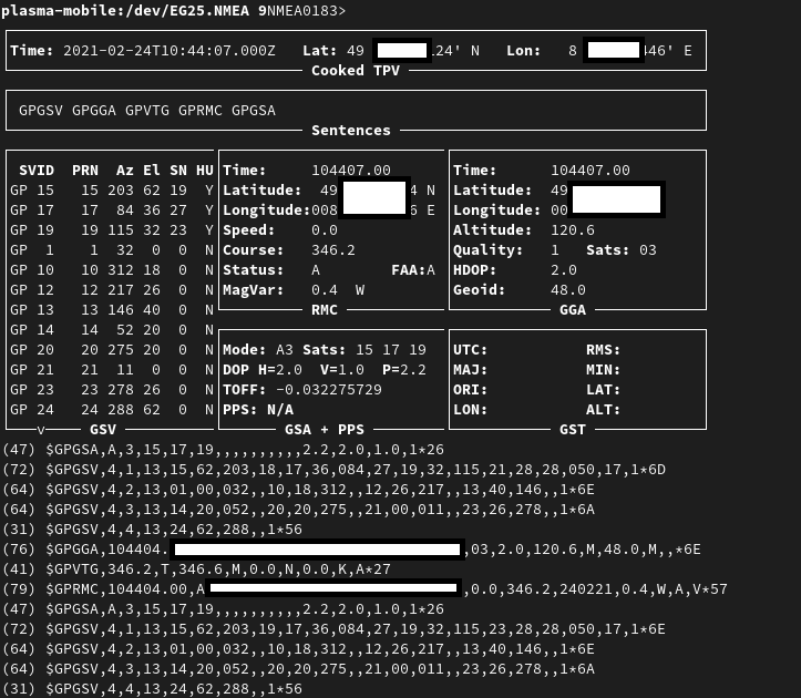
gpsmon decoding GPS data from /dev/ttyUSB1
To check if GNSS data output is enabled, you can
cat /dev/ttyUSB1
this should display a stream of NMEA sentences
$GPVTG,,T,,M,,N,,K,N*2C
$GPGSA,A,1,,,,,,,,,,,,,,,,*32
$GPGGA,,,,,,0,,,,,,,,*66
Further details can be found under Sensors and navigation.
Voice mail
The operating systems of the PinePhone may not have support for accessing your voicemail by holding down the 1-key. Carriers might support accessing the voice mail via an external number however.
APN settings
The APN setting is the gateway between your carrier’s cellular network and the public Internet. The APN setting - if not set automatically by the user’s OS - has to be set by the user to enable the use of the mobile Internet on the phone.
Setting the APN
The location of the APN setting depend on the user interface the distribution is using.
Gnome
One of the biggest actively maintained open (Creative Commons Public Domain) database of mobile broadband service providers and their APN settings is maintained by the Gnome project, and is available in their serviceproviders.xml. It is a rare case, when you don’t find your own provider in that list, but if it happens, then please consider contributing to it upstream. If your provider is in that database, then for setting up the APN, you only have to select your provider from the list under Settings > Network > Network Dropdown > Add new connection.
Further details are described by the Gnome help.
Phosh
The APN settings are either located under Settings > Mobile > Access Point Names or Settings > Network > Network Dropdown > Add new connection.
Plasma Mobile
The APN settings are located under Settings > Cellular Networks > SIM 0 > Modify APNs. While this is an auto-detect button, some cell providers may be detected incorrectly. Additionally, the settings for MMS are located under Spacebar > Settings > Multimedia Messages (MMS).
Carrier support
Please help to review and edit this page or section. Information are subject to change.
This page contains hints on setting up cellular network connectivity for specific carriers. For more general information, see the carrier support section of PinePhone. For the APN settings see APN settings.
Check compatibility
To check if the PinePhone is supported on your carrier:
Search for your carrier on frequencycheck.com and compare the carrier’s LTE/GSM/WCDMA frequencies to the PinePhone’s supported frequencies (listed in the https://wiki.pine64.org/wiki/File:Quectel_EG25-G_LTE_Standard_Specification_V1.3.pdf modem specification sheet).
It is likely that there will be a few frequencies that your carrier uses which are not supported by the PinePhone. Not all of the carrier’s frequencies need to be supported by the PinePhone for it to work - as long as most of them are supported, you will still get good coverage.
MMS workarounds
These scripts allow partial MMS support on a PinePhone in distributions without working MMS support:
- JMMS: https://git.sr.ht/~amindfv/jmms
- silvermms: https://gitlab.com/5ilver/silvermms
- MMS via Matrix with mmmpuppet: MMS with Matrix
There is a Haskel MMS client. MMS can also be manually composed with mmsd on the command line.
Privacy switches
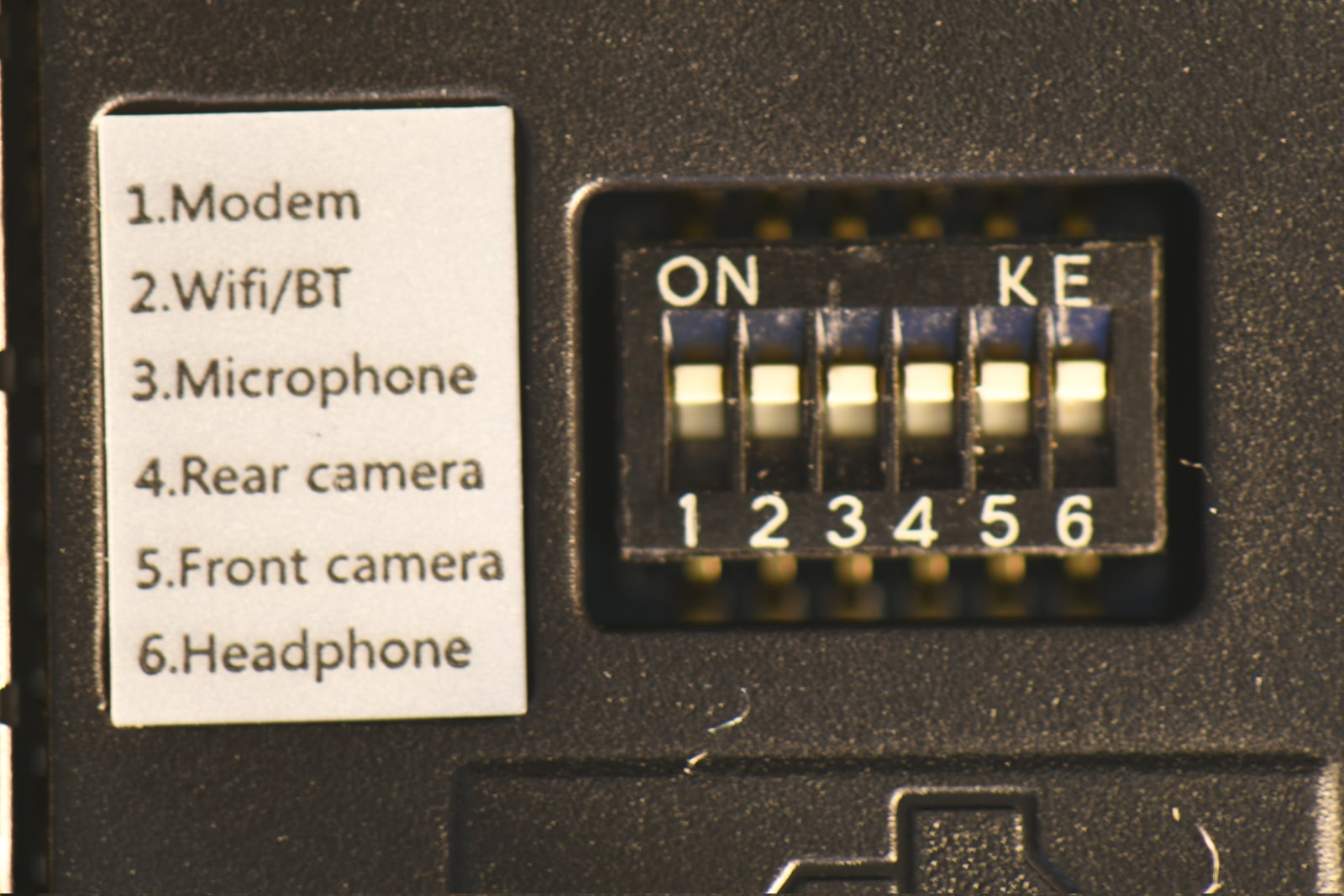
Picture of the privacy switches
The PinePhone features six switches that can be used to configure its hardware. They are numbered 1-6, with switch 1 located nearest to the modem. Their “on” position is toward the top of the phone.
| Number | Name | Explanation | Description |
|---|---|---|---|
| 1 | Modem | Pulls Q1501 gate up (FET killing modem power) | “On” enables 2G/3G/4G communication and GNSS hardware, “off” disables it. |
| 2 | WiFi / Bluetooth | Pulls up CHIP_EN | “On” enables WiFi and Bluetooth communication hardware, “off” disables it. |
| 3 | Microphone | Breaks microphone bias voltage from the SoC | “On” enables audio input from on-board microphones (not 3.5 mm jack), “off” disables it. |
| 4 | Rear camera | Pulls up PWDN on OV5640 | “On” enables the rear camera, “off” disables it. |
| 5 | Front camera | Pulls up PWDN on GC2145 | “On” enables the front camera, “off” disables it. |
| 6 | Headphone | Pulls up IN2 on analog switch BCT4717ETB | “On” enables audio input and output via the 3.5 mm audio jack, “off” switches the jack to hardware UART mode. |
Repairs
Spare parts not available in the Pine Store
The following parts are not available for purchase in the Pine Store, however compatible parts can be sourced from other shops:
- Earpiece speaker dimensions: 12x6x2 mm. Compatible with Xiaomi Mi2 / Mi3 (but not Mi4!) and others, see here
- Loudspeaker dimensions: 15x11x3 mm. Compatible with Nokia N91, Lenovo A536 (requires soldering) and others, see here
- Proximity sensor rubber isolator
Earpiece speaker
The earpiece speaker refers to the small speaker at the top of the PinePhone and PinePhone Pro.
This part is not available to purchase from the PINE64 Store. However, it is possible to buy a replacement earpiece for another device, and install it in a PinePhone or PinePhone Pro. This documents earpieces that have been tested by the community, and verified to work.
Note that the earpiece dimensions for both the PinePhone and PinePhone Pro are 12x6x2 mm. When looking into earpieces not found in this list, aim for these dimensions.
Compatible earpiece speaker
| Model | PinePhone | PinePhone Pro | Example shop |
|---|---|---|---|
| LG K8 2017 M200N | Kind of ¹ | Broken | |
| Nokia 5 | Works | Works | |
| Nokia 7 | Works ² | Works ² | Replace Base |
| Nokia X5 | Works | Works | |
| OnePlus One | Works | Works | iFixit, Replace Base |
| OnePlus X | Works | Works | Replace Base |
| PinePhone | Works | Works | |
| Xiaomi Mi A1 | Works | Works | Replace Base |
| Xiaomi Redmi Note 4 | Works | Works |
Notes:
¹ The earpiece is too thin, it can work with padding to keep the contacts together.
² Audio playback is very low quality.
Incompatible earpiece speakers
The following devices are known to have replacement earpiece speakers with dimensions too large to fit inside the PinePhone or PinePhone Pro.
- Blackberry Classic Q20
- HTC Desire 500
- HTC M10
- Huawei Honor 7A
- Huawei Mate 10 Pro
- Huawei Y7 Prime 2018
- OnePlus 2
- Oppo Reno 5 4G
- Sony Xperia X Compact
- Sony Xperia XA1 Ultra
- Sony Xperia XP X Performance
- Sony Xperia XZ
Replacing the mainboard
The mainboard can be replaced if it is faulty. The replacement board does not have an operating system pre-installed, to test if everything is working after swapping the mainboard a flashed microSD card is required.
Prior to replacing your PinePhone’s mainboard please read the steps outlined in bullet points below and watch the attached video.
- You’ll need a small Phillips screwdriver and a prying tool to swap out the mainboard.
- Remove the PinePhone’s back cover. See your quick start guide for details.
- Remove the battery as well as any inserted SD and SIM cards.
- Unscrew all 15 Phillips head screws around the midframe of the phone.
- Gently pry up the midframe using a guitar pick or credit card corner. It is easiest to separate the midframe at one of the bottom edges. Work your way around all the sides of the phone until the midframe separates from the phone’s body.
- Detach all ribbon cables and “Lego” connectors. List of things to detach: 1) two “Lego” connects at the bottom of the mainboard. 2) u.FL antenna connect and touchscreen digitizer on PCD left side. 3) LCD ribbon cable top of mainboard, next to audio and UART jack.
- Pry the mainboard up gently from the left-hand side.
- Remove front and main cameras and reset them into the new mainboard.
- Check that the rubber proximity sensor housing is in the chassis, not stuck to the removed mainboard.
- Place the new mainboard in the chassis, hooking in on the plastic tabs on left side and pressing down firmly on opposite side, and follow the steps (7-2) in reverse. When reattaching the midframe take care that no cables are out of place or trapped, as they may be damaged when tightening screws.
After swapping the mainboard the phone won’t boot as there is no OS on the replacement board’s eMMC preinstalled. To boot an OS insert a flashed SD card.
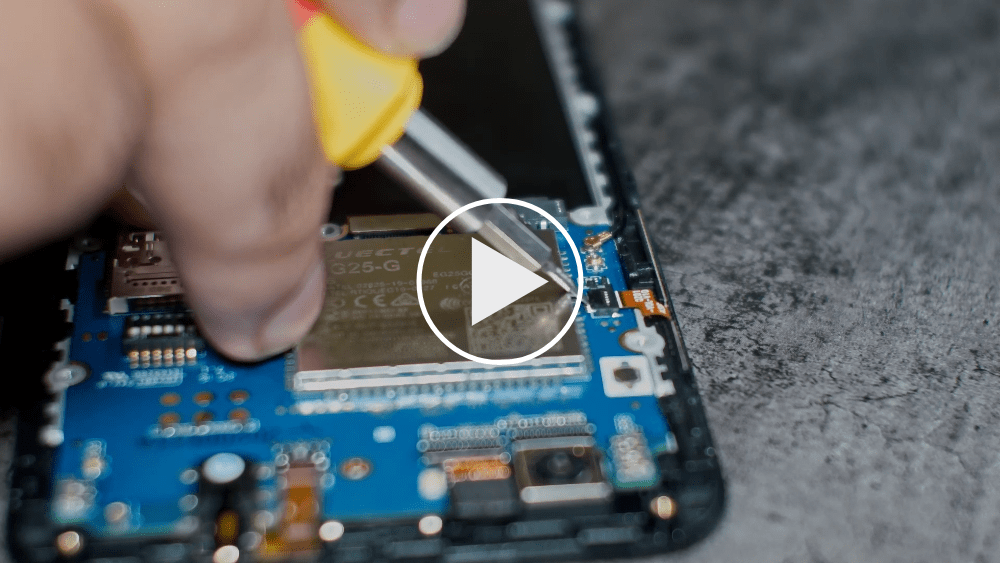
A video tutorial by Martijn Braam can be found here (or alternatively a video tutorial by user brigadan with additional notes about the camera swap and proximity sensor isolator here):
Flashing the ANX firmware
Method 1
After swapping the mainboard the ANX7688 chip has to be flashed for full USB functionality.
Under GNU/Linux this can be done by downloading the latest ANX7688 firmware image on the phone:
wget https://xff.cz/git/linux-firmware/plain/anx7688-fw.bin
and executing as root (“sudo su”) on the phone:
cp anx7688-fw.bin /lib/firmware/
echo 1 > /sys/class/typec/port0/device/flash_eeprom
Method 2
Booting a factory test image will automatically flash the ANX7688 chip. See Factory Test OS for such an image.
Replacing the screen
Before attempting to replace the screen be sure to review the section on replacing the mainboard since that will get you most of the way there. Be aware that the replacement screen is actually the entire front frame of the phone and there are components that will need to be swapped from your old screen.
- Make sure you have a precision screwdriver set that has the correct size Philips tip. The screws are very small and the heads can easily be stripped if the screwdriver is not correct - if you feel your screwdriver slipping, stop what you are doing and try one that is a better fit. A magnetized screwdriver will help in not losing screws, as will a magnetic parts holder to keep them in while working.
- There are a number of components and cables as well as the insulator sheet under the battery that are glued in place. A hair dryer will loosen the glue and make them much easier to remove. You may want to order extra cables along with the screen just in case.
- The vibration motor, which is part of the USB-C board assembly and glued into place, will come apart easily and be damaged if you pry it up in the wrong place. Make sure you pry from underneath the complete part, not midway on its housing. The ribbon cable attaching this to the USB-C board is small, thin, and fragile so be careful with that as well.
- The new screen comes with new side switches and insulator sheet but there are a number of parts that need to be transferred from the old screen, like the thin coax cable running up the side, the phone ear speaker, proximity sensor gasket, and a gold-colored mesh glued in place that needs to be transferred to a flexible circuit included on the new screen. If you don’t swap over the proximity sensor rubber gasket the screen will immediately turn off after logging in. Be careful when routing the coax cable that it goes around the screw holes or you may drive a screw right through the cable.
Take your time, use the right tools, be careful and you should be rewarded with success.
Hardware issues
SIM reader
The SIM reader may fail to read a SIM card (reporting ‘sim-missing’ in mmcli), possibly due to deformed pins (if you put your SIM adapter in without a SIM), or due to a warped SIM card adapter.
A possible solution is to bend the pins back (using a plastic spudger), and/or use a different SIM card adapter (which your carrier may provide to you).
USB-C side board
Many issues with the USB-C side board can be fixed by replacing the USB-C side noard
Internal microphone
The microphone may stop working or occasionally stop working or give off static when power is plugged in.
One possible fix is to shim U101 (as seen on the back side of the USB-C side board) with a piece of paper or cardboard, see https://wiki.pine64.org/wiki/User:Earboxer/Shim_U101.
Bottom speaker
The bottom speaker may stop working, especially if you have recently mishandled the USB-C side board, stressing the point of connection between the circuit board and the circuit flex. This can be fixed by touching up the solder between the two.
Mods
There are a number of options to hardware mod the PinePhone.
Some are upgrades to fix issues that were not done optimally in the production of that version of the electronics, and some are to add options that were not part of the phone spec.
General
Make pictures of the situation before and after your mods, so you can compare the change, and don’t need to disassemble the device to get the right pics later.
Laser-cut parts
User Mcyam2 has created some laser-cut templates for the rear facing components here:
https://anonfiles.com/L0BeK5L5oe/ppsvg-backplate-CUTOUT_svg
Originally based on silver’s work on a 3d printed rear frame
3D-printed parts
Silver has created a 3D-printable rear frame for the PinePhone and used it to create a folding keyboard design (work in progress), User:Silver/3d printed a folding keyboard mostly.
https://www.youmagine.com/designs/pinephone-folding-keyboard-mockup
PCBs
https://github.com/SMR404/PinephonePogoBreakout
https://github.com/jnavarro7/pinephone_flex_breakout_board_grove
Braveheart Edition
- PMIC mod - Stops the battery drain from a shutdown phone, draining the battery to 0V.
- VCONN mod - Unblocks the USB-C power negotiation rail, so convergence functions are unlocked.
PMIC mod
PinePhone 1.1 VBUS power usage hardware fix
The original description of this fix is given on megi’s pager here https://xnux.eu/devices/pp-pmic-fix.jpg
VCONN mod
See below.
Braveheart Edition and UBPorts Community Edition
- VCONN mod - Unblocks the USB-C power negotiation rail, so convergence functions are unlocked.
There are also a number of mods that can be done adding more functions by adding extra hardware to the pogo pins, and a number of options to change the screen protector.
At this moment there are not many pogo addons, and most are just connector boards. Likely the makers will add links to these projects to this page. Pine is looking into adding a N900 style keyboard attached to these pins.
VCONN mod
The original description of this fix is given on megi’s pager here https://xnux.eu/devices/pp-usbc-fix.jpg There is a discussion on the merits of the different ways to do the fix.
VCONN mod, Removal only
PinePhone 1.2 VCONN hardware fix
There are now a few documented ways,
- Removal only, the tweezer “stupid” way: https://www.youtube.com/watch?v=j3jc7Mvn9Eo
- Removal only, the soldering iron “less stupid” way: https://www.youtube.com/watch?v=ZqOb45N2sMc
There are hopefully videos coming doing it the proper way, and so they can be linked here.
After this the firmware for the power negotiation chip needs to be upgraded, this can be done by running the factory test image, version https://images.postmarketos.org/pinephone/pine64-pinephone-20200724-factorytest55.img.xz or higher. This will do the firmware flashing and respond with a message indicating the state. After this the phone is ready for its added functions. ANX states:
- No CC Fix - Fix not applied
- No USB Cable - No USB-C connection, cannot upgrade firmware
- OK - Firmware Applied, you are all set
VCONN mod, Replacement
Using 2x NCP334FCT2G you could do the full fix, making VCONN powered devices able to negotiate power. IT needs the parts to be removed first without damaging the pads, and then replacing the parts.
Further mods
PinePhone 1.1 VBUS power usage Hardware Fix
This page details a hardware fix for an issue that affects some early v1.1 Braveheart units (fixed since 1.2 community edition included).
The issue was PinePhone_v1.1-Braveheart#Excess_power_usage_while_driving_VBUS by megi.
TODO: Add more pictures and schematics, better reference the fix origin and tradeofs, remove TODOs/FIXMEs.
Affected Units
FIXME: confirm “Project Don’t Be Evil” devkit and PinePhone v1.0 - Developer batch are unaffected.
Disclaimer
Though easier to perform than the PinePhone 1.2 VCONN hardware fix, this fix requires desoldering relatively small Surface Mount Technology (SMT) components, therefore some experience with soldering is recommended.
Issue description
TODO: pictures
The AXP803 cannot detect when the USB port is powered by the battery. Therefore, the Power Management IC (PMIC) continues draining current from it. This is especially problematic since this USB port is powered from the battery with the USB OTG boost regulator. One of the symptoms is the battery discharging rather quickly even when the phone is powered off.
Workaround
HW workaround is desoldering the U1301 regulator (TODO: describe its role) and shorting pads for R1309 on the PCB (this is a “0 ohm” resistor on the schematic, so it’s completely fine).
Shorting the pads is easy to do with some solder (while carefully avoiding to short it with nearby resistors).
Desoldering the regulator is harder to do, since its large pads are designed to use the PCB as a heatsink and will happily cool down while you are trying to melt it. It should be possible to use properly sized pliers to cut the pins first, please edit if you attempt this.
Please be careful not to overheat nearby components trough the PCB traces when applying heat to the regulator. It can be helpful to start the operation with melting some leaded solder tin together with the pads, and lifting the regulator while applying heat also helps. Start with the side that has only one pad: though it is bigger, it should be easier to lift up. It might be useful to apply a relatively large quantity of molten solder tin to each pin, in turn, while lifting the regulator, to reduce the PCB heatsink effectiveness.
Feel free to add your experiences and tips here.
Tradeoffs
TODO: Unknown to the author
Proper fix
TODO
Sources and tutorials
- Tutorial from megi
- Description from megi at the end of the page
PinePhone 1.2 VCONN Hardware Fix
This page details a hardware fix for an issue that was found on early PinePhone hardware revisions (see PinePhone for an overview of the different revisions) and has been fixed since the 1.2a hardware revision.
The issue was PinePhone_v1.1-Braveheart#USB-C_CC_pins_are_pulled_to_the_GND_by_AW3512.28VCONN_switches.29_when_VCONN_is_off_ by megi.
Affected Units
- Requires confirmation: “Project Don’t Be Evil” devkit
- Requires confirmation: PinePhone v1.0 - Developer batch
- PinePhone v1.1 - Braveheart
- PinePhone v1.2 - UBports Community Edition
Disclaimer
This fix requires desoldering tiny (1 mm per 1 mm, from the datasheet) BGA components, therefore some experience with soldering is highly recommended.
Issue description
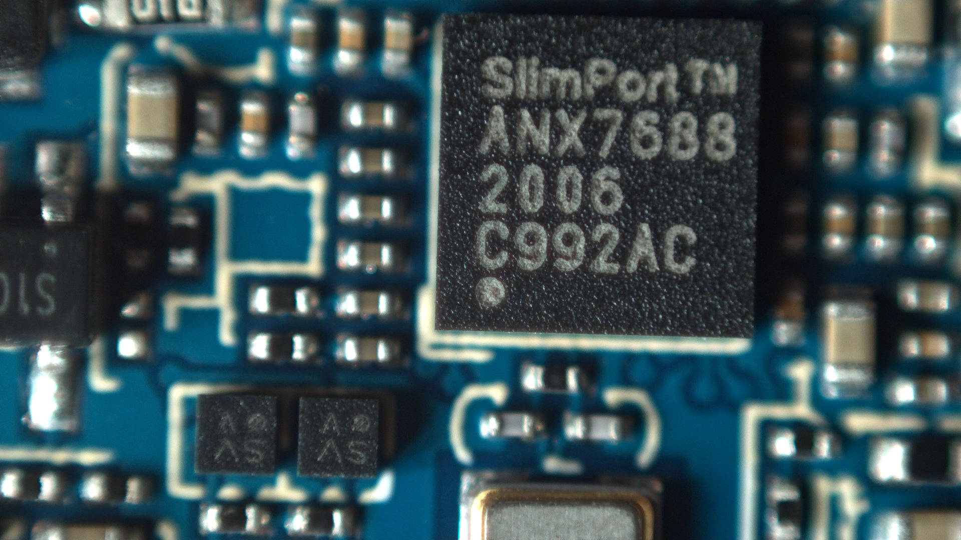
Close-up picture of the two identical switches the issue originates from, with the ANX USB controller in the frame

Excerpt from the PinePhone schematic showing the two components.
The USB standard specifies that both halves (top and bottom) of the USB-C port contains one “CC” pin (CC1 and CC2, respectively). A regular cable will connect a CC pin from one end to the other end. This allows detecting which way the cable is plugged. Some active USB-C cables exist (both “e-marked” and “managed active cables”); they contain a chip, which needs to be powered. This is done by having one of the cable end connect its CC pins to 5V and VCONN, and requires switches to plug the right CC pin to the right voltage.
The issue arises due to the switches that were chosen up to v1.2a (the a revision excluded) of the PCB assembly: the infamous AW3512, labelled U1305 and U1309 on the schematic. Instead of leaving the output pin “dangling” with a high impedance when disabled, the switch pull the output down. This feature is intended for discharging a capacitor, hence its “Quick output discharge” name. This is an excerpt from the datasheet:
“The AW3512/AW35122 includes the Quick Output Discharge (QOD) feature, in order to discharge the application capacitor connected on OUT pin. When EN pin is set to low level (disable state), a discharge resistance with a typical value of 276Ω (AW35122: 75Ω) is connected between the output and ground, pull down the output and prevent it from floating when the device is disabled.”
This issue prevents cable plug/orientation detection and USB-PD communication. ANX always sees cable as plugged even if none is plugged. There’s no SW workaround for automatic detection of cable plug or power role.
In SW this could theoretically be worked around by manual selection of PinePhone’s data and power role by the user, but hasn’t been attempted, and might damage hardware if done incorrectly.
Workaround

Hardware workaround is desoldering U1305 and U1309 switches (BGA like packages). This will void the VCONN control, but it will release the CC pins for their proper connection detection and negotiation roles.
Tradeoffs
Voiding the VCONN control might (TODO: gather more data) prevent some accessories from working, notably those using an active cable.
Proper fix
HW fix is to replace AW3512 with a variant of the chip that preserves the EN signal polarity and that doesn’t have the “quick discharge function” that ties the output to the GND via a 75 Ohm resistor when the switch is OFF. mozzwald used NCP334FCT2G as a replacement. PCBA revision 1.2a onwards incorporate that fix.
Sources and tutorials
- megi’s writeup
- another writeup from megi with a few words on firmware
- Video: “The right way” with a hot air gun/reflow station, by mozzwald
- Video: “The equally stupid way”, workaround video by Dalton, using a soldering iron. Less chances to permanently damage the board than the next if you are handy with a soldering iron, but still high.
- Video: “The stupid way” workaround video by Lukasz, with pliers. Slightly damages the circuit board, preventing you from soldering the replacement chips at a later point. You might be fine with this.
PinePhone 1.2b R1318 backlight Hardware Fix
This page details a hardware fix for an issue that was found on early PinePhone hardware revisions (see PinePhone for an overview of the different revisions) and has been fixed since the 1.2b hardware revision.
Affected Units
- PinePhone v1.2 - UBports Community Edition
- PinePhone v1.2a - postmarketOS Community Edition
Disclaimer
This fix requires desoldering a tiny resistor, therefore some experience with soldering is highly recommended.
Issue description
When connecting a VBUS powered device to the affected devices, like USB-C docks or hubs, the brightness changes significantly. The cause of the issue was a VBUS_CTRL signal provided by ANX7688 to control VBUS power direction. The signal is connected to AXP803 to tell it to not trying to charge from VBUS when the VBUS is generated from the battery. The signal is connected to the PL9 pin of the SoC, withut there being a reason for that. VBUS_CTRL is a 3.3V signal and the PL port is a 1.8V port. The issue was introduced in the 1.2 board revision.
Fix
The fix of the issue is to remove the R1318 resistor.
A detailed instruction will follow here.
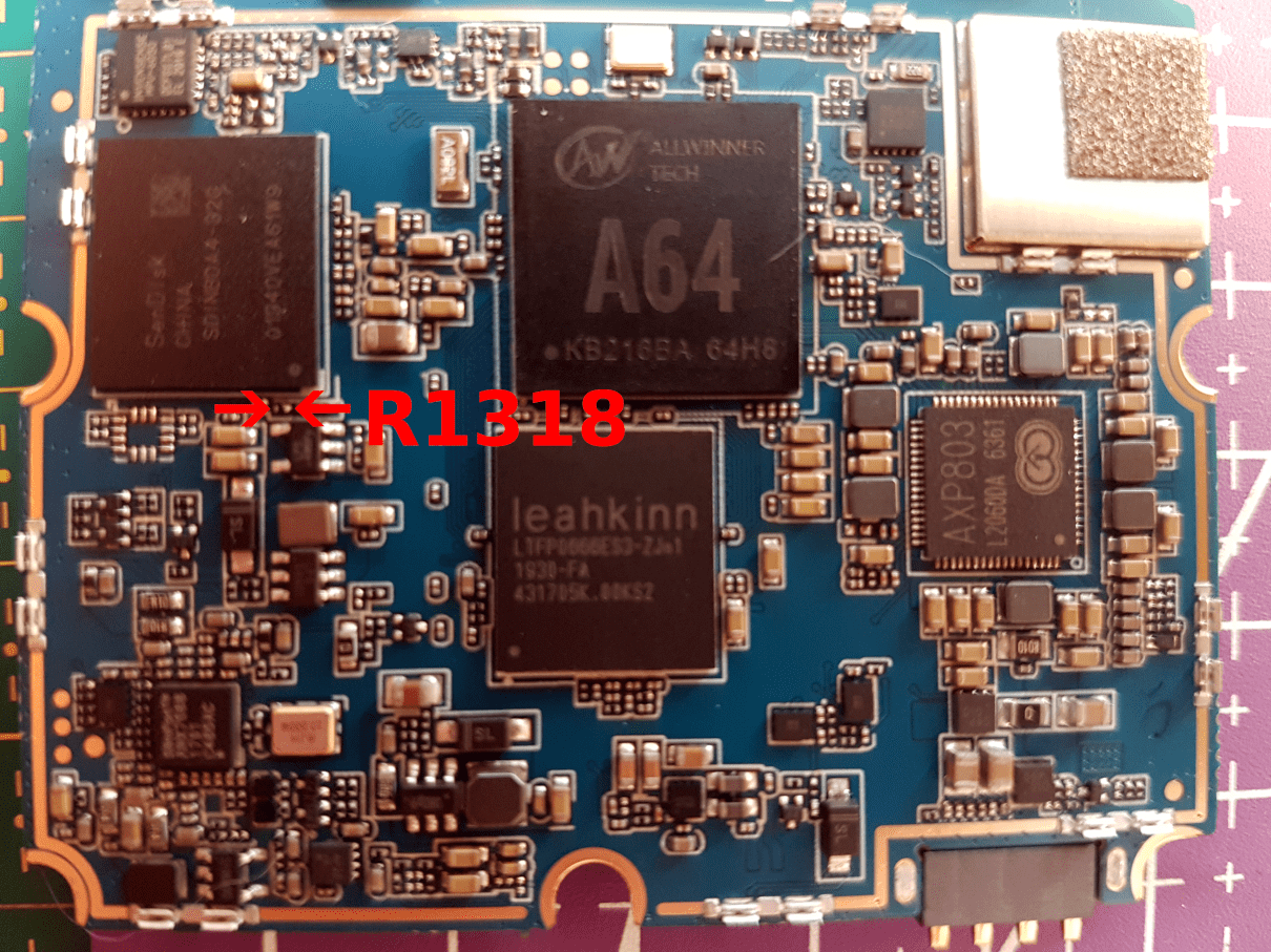
R1318 location on the board
Sources and tutorials
Software tricks
Security
Please help to review and edit this page or section. Information are subject to change.
Encryption
While encryption alone is not sufficient to protect sensitive data, it is an important tool to safeguard data in certain attack vectors.
Full-Disk Encryption
Full-disk encryption encrypts the entire disk (except for the boot bits). Currently some operating systems such as postmarketOS and Mobian offer an installation image, which have the option to encrypt the entire disk. Some operating systems, such as postmarketOS (via pmbootstrap) and Arch Arm also offer an installation script for an fully encrypted installation.
Decryption is done at boot after entering the encryption password via an on-screen keyboard (Osk-sdl).
Encrypted home directory
SSH
An open SSH port is a typical gateway for attackers on any device exposed to the public Internet. Exposed devices might be attacked within minutes after being exposed. Typically such attacks try default passwords such as “12345”, potentially putting the user at risk after connecting the phone to an open/unsecured access point, activating mobile data or mobile Internet.
For safety reasons it is highly recommended to only use SSH in combination with keys, instead of simple numeric passwords.
To generate a key pair for ssh, open a terminal on your local computer, and type
ssh-keygen
It will ask you where to save the key pair. By default, this is in ~./ssh . Usually it’s best to keep it in the default location. If you have previously generated a key pair, it will ask you if you wish to overwrite your existing one. You probably do not want to do this, as you will no longer be able to use your existing key pair for authentication.
Next, you will be prompted to enter a passphrase. It is recommended that you use this feature.
Now, you must start SSHD on your distribution of choice, as this process varies depending on init system, please consult the documentation of your distribution.
Now enabled, you can copy over your public key either manually, or via
ssh-copy-id $username@$ipaddress
replacing the variables “$username” and “$ipaddress” with the appropriate values, e.g user@192.168.1.15
You may see a message similar to this
Output
The authenticity of host '192.168.1.15 (192.168.1.15)' can't be established.
ECDSA key fingerprint is fd:fd:d4:f9:57:fe:23:44:e1:55:00:bd:d6:6d:42:fe.
Are you sure you want to continue connecting (yes/no)?
This will happen anytime you connect to a new host. Type “yes” and hit enter.
finally, to disable password authentication, type
sed -i -E 's/#?PasswordAuthentication yes/PasswordAuthentication no/' /etc/ssh/sshd_config
as root on your PinePhone and either restart the sshd service, or reboot your device
Crust
As per the README.md on the crust github:
Crust improves battery life and thermal performance by implementing a deep sleep state. During deep sleep, the CPU cores, the DRAM controller, and most onboard peripherals are powered down, reducing power consumption by 80% or more compared to an idle device.
For this to work, Crust runs outside the main CPU and DRAM, on a dedicated always-on microprocessor called a System Control Processor (SCP). Crust is designed to run on a specific SCP implementation, Allwinner’s AR100.
To build crust manually with U-Boot you can find instructions Here.
RTC wakeups
It is possible to set the device to wakeup at a specific time or after a certain number of seconds using rtcwake: rtcwake -m mem -s 10
This example will put the device to sleep for 10 seconds and then wake it up. More information on the rtcwake command can be found in the man pages
Manual suspend
For manually suspending the device on distributions with Systemd you can use the following command with super user permissions: systemctl suspend
On non-systemd distributions you can directly echo: echo mem > /sys/power/state
MMS with Matrix
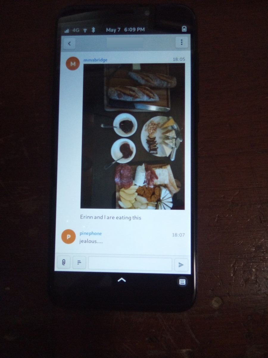
Screenshot of fractal displaying an MMS conversation
The one known way to get MMS fully (meaning pictures and group messages) working is by relaying all SMS and MMS to a matrix server and using a matrix client to interact with them. https://gitlab.com/untidylamp/mmmpuppet is the bridge used here
Outgoing messages over the max size are sent as a link. The link will not resolve if matrix is hosted on the PinePhone itself, so resize your images. An easy way might be to take a screenshot of your image viewer and send that image instead.
This method works with a local-to-the-pinephone matrix server but you could instead use a public one on the internet. Free accounts on matrix.org should work fine for example. Sleep may need to be disabled for non-local servers or the bridge can get stuck.
Install packages
Arch
Start with a nice and up-to-date Danctnix’ Arch ARM PinePhone installation, mine is from April 20 2021. SSH into the PinePhone and then run this to install all the needed packages
sudo pacman -Sy matrix-synapse fractal python-matrix_client python-gobject git meson ninja base-devel python-matrix-nio python-dbus
Start the service
sudo systemctl enable synapse
sudo systemctl start synapse
Mobian
Flash a fresh mobian nightly (Tested September 28 2021) and install the following:
sudo apt install matrix-synapse fractal mmsd-tng python3-matrix-nio python3-vobject python3-aiofiles git
Set up Matrix Synapse on localhost
Skip this if you will be using a remote homeserver. Make a new config with the server name set to local host.
Arch
cd /etc/synapse/
sudo python -m synapse.app.homeserver --server-name localhost --config-path homeserver.yaml --generate-config --report-stats=no

sudo vi /usr/lib/systemd/user/matrix-synapse.service
Description=Multimedia Messaging Service Daemon
After=ModemManager.service

ExecStart= python3 -m synapse.app.homeserver --config-path=/etc/matrix/homeserver.yaml

Restart=on-failure
RestartSec=10s

WantedBy=default.target
Start the service
systemctl enable matrix-synapse --user
systemctl start matrix-synapse --user
Mobian
cd /etc/matrix-synapse/
sudo rm homeserver.*
sudo python3 -m synapse.app.homeserver --server-name localhost --config-path homeserver.yaml --generate-config --report-stats=no
sudo service matrix-synapse start
Add new matrix users
in /etc/synapse/ (arch) or /etc/matrix-synapse/ (mobian)
register_new_matrix_user -c homeserver.yaml http://localhost:8008 # New user name and pw will both be pp
register_new_matrix_user -c homeserver.yaml http://localhost:8008 # New user name and pw will both be mm
Open fractal and log into the homeserver at http://localhost:8008 with username pp and password pp
Set up MMSD
From git
Note: historical, no longer needed, mmsdtng commonly packaged
Grab the git repository and install it:
cd ~
git clone https://source.puri.sm/kop316/mmsd.git
cd mmsd
meson _build
meson compile -C _build
meson test -C _build
sudo meson install -C _build
sudo vi /usr/lib/systemd/user/mmsd-mm.service
Description=Multimedia Messaging Service Daemon
After=ModemManager.service

ExecStart=/usr/local/bin/mmsd -n -d

Restart=on-failure
RestartSec=10s

WantedBy=default.target
sudo chmod 644 /usr/lib/systemd/user/mmsd-mm.service
systemctl enable mmsd-mm.service --user
systemctl start mmsd-mm --user
Settings for T-Mobile
This config works for me
After starting mmsdtng the first time it should generate a config. Edit the following 3 options:
vi ~/.mms/modemmanager/ModemManagerSettings
CarrierMMSC=http://mms.msg.eng.t-mobile.com/mms/wapenc
MMS_APN=fast.t-mobile.com
AutoProcessSMSWAP=true
Restart MMSD ModemManager service
systemctl restart mmsdtng
Install MMS bridge
Grab it from git and put things in places
cd ~
git clone https://gitlab.com/untidylamp/mmmpuppet.git
cd mmmpuppet
chmod +x mmmpuppet.py
sudo cp mmm*.py /usr/local/bin/
mkdir -p $HOME/.config/mmm/
cp conf.json.sample $HOME/.config/mmm/conf.json
Configure MMS bridge
This will mostly take care of editing the config for you if you are running a local matrix server.
sed -i 's^"https://matrix-client.matrix.org"^"http://localhost:8008"^' $HOME/.config/mmm/conf.json
sed -i 's^"@bot_account:matrix.org"^"@mm:localhost"^' $HOME/.config/mmm/conf.json
sed -i 's^"Change_me"^"mm"^' $HOME/.config/mmm/conf.json
sed -i 's^"@your_accounts:matrix.org"^"@pp:localhost"^' $HOME/.config/mmm/conf.json
You actually have to fill these two out yourself. I put “US” and my +1 and rest of 10 digit number.
vi $HOME/.config/mmm/conf.json
"cell_number":      "+15554441234",
"cell_country":     "CA",
Now we need to run it once to process the config file and remove secrets (It will say it has done this and exit on first run)
/usr/local/bin/mmmpuppet.py
check it out now
cat $HOME/.config/mmm/conf.json
If it doesn’t change the file to remove all the linebreaks then it didn’t like it. Figure out why by looking at the log file.
cat ~/.config/mmm/mmmpuppet.log
Go fix whatever went wrong. Which should be nothing. You should have seen a message like this as output before it returns you to a prompt:
Login successful. Config updated with token. Run again to start bridge.
Set up MMS bridge service
Make systemd unit
sudo vi /usr/lib/systemd/user/mmmpuppet.service
Description=Starts mmmpuppet interface
After=mmsd-mm.service

ExecStart=/usr/bin/python3 /usr/local/bin/mmmpuppet.py
Restart=on-failure
RestartSec=10s

WantedBy=default.target
and start it
sudo chmod 644 /usr/lib/systemd/user/mmmpuppet.service
systemctl enable mmmpuppet.service --user
systemctl start mmmpuppet.service --user
See if services are running:
ps aux | grep mm
It should show something like this even after reboot
alarm       6374  0.0  0.3 235364  7752 ?        Ssl  22:44   0:00 /usr/local/bin/mmsd -n -d
alarm       6825  9.8  2.7 224976 54188 ?        Ssl  22:52   0:05 /usr/bin/python3 /usr/local/bin/mmmpuppet.py
Remove Chatty
For Arch use Pacman to remove Chatty.
Mobian:
apt remove chatty
Don’t forget to enable data
You can get SMS but not MMS with mobile data off
Launch fractal
Log in with this homeserver: http://localhost:8008. Username is pp and password is pp.
Logins are not saved. You need to add a new item named login to the gnome keyring manually to fix it. See: https://wiki.mobian.org/doku.php?id=fractal
Basically apt install seahorse, open “passwords and keys” in the app drawer, click new (plus), select password keyring, and name it “login” (all lower no quotes). Then autologin will work as it should.
Done
At this point if you get a message a new room should be created by the bridge bot which you will be invited to. You can start a new conversation by creating a new room, setting the topic with phone numbers of participants, and then inviting the mm user. See the mmmpuppet readme for examples.
Other clients
quaternion also seems to work but has clunky UI issues. Might work better with scaling
Power Management
The data on this page is based on the the PinePhone v1.1 - Braveheart.
Regulators
Current Assignments
| Name/GPIO | Output Voltage | Can disable at runtime? | Can disable in suspend? | Consumers (internal/external separated by semicolon) |
|---|---|---|---|---|
| DCDC1 | 3.3V | No | No (VCC-IO) | VCC-EFUSE, VCC-IO, VCC-PC (VQMMC2), VCC-PD, VCC-USB; Modem [I2C, PCM, UART], Motor, Pogo I2C, UART0, VMMC0, VMMC2, WiFi CHIP_EN |
| DCDC2 | DVFS | No | Yes | VDD-CPUX |
| DCDC3 | DVFS | N/A | N/A | VDD-CPUX (polyphase with DCDC2) |
| DCDC4 | N/A | Yes | Yes | Not used |
| DCDC5 | 1.2V | No | Yes (future) | VCC-DRAM; DRAM |
| DCDC6 | 1.1V | No | Yes (future) | VDD-SYS |
| DC1SW | N/A | Yes | Yes | Not used |
| ALDO1 | 2.8V | Yes | Yes | VCC-PE; Camera AFVCC, Camera DOVDD, CSI I2C, Pogo I2C |
| ALDO2 | 1.8V | No | No (VCC-PL) | VCC-PL; Pogo INT |
| ALDO3 | 3.0V | No | No (KEYADC) | AVCC, KEYADC, VCC-PLL |
| DLDO1 | 3.3V | No | No (ANX7688 AVDD33) | HVCC, VCC-DSI; ANX7688 [AVDD33, HDMI_VT, I2C, ANX-V1.0 Enable, VCONN_EN Disable Pull-up], HDMI [DDC, HPD], Proximity LED, Sensor I2C, Sensor VDD |
| DLDO2 | 1.8V? 3.3V? | Yes | Yes | MIPI-DSI VIO |
| DLDO3 | 2.8V | Yes | Yes | Camera AVDD |
| DLDO4 | 1.8V-3.3V | Yes | Yes | VCC-PG; VQMMC1 |
| ELDO1 | 1.8V | No | No (DRAM) | CPVDD; DRAM |
| ELDO2 | N/A | Yes | Yes | Not used |
| ELDO3 | 1.8V | Yes | Yes | Camera DVDD |
| FLDO1 | 1.2V | Yes | Yes | HSIC-VCC (not used) |
| FLDO2 | 1.1V | No | No (VDD-CPUS) | VDD-CPUS |
| GPIO0-LDO | 3.3V | Yes | Yes | Backlight PWM, LCD, Proximity sensor VDD, Touchscreen [I2C, VCC] |
| GPIO1-LDO | 1.8V | No | No (ANX7688 DVDD1V8) | ANX7688 [AVDD1V8, DVDD1V8, CC, HDMI DDC, I2C, Power/Reset pull-up] |
| PD6 | 5.0V | Yes | Yes | USB OTG |
| PD8 | 5.0V | Yes | Yes | Pogo supply, USB OTG via PD6 |
| PD9 | 5.0V | Yes | Yes | VCONN (USB Type C) |
| PH10 | PWM | Yes | Yes | Backlight |
| PL7 | VBAT | Yes | Yes | Modem |
| ANX-V1.0 | 1.0V | Yes | Yes | ANX7688 [AVDD1V0, DVDD1V0] |
Suggested Regulator Hardware Changes
ANX7688
- Move ANX7688 AVDD33 (the chip input only, not the other things connected to 3v3) and ANX7688 I2C Level Shift (3.3V side) from DLD01 to DCDC1, and ANX7688 VCONN_EN Disable Pull-up (R1355 and R1366) from DLDO1 to ANX1.8V
Move ANX7688 ANX1.8V from GPIO1-LDO to ALDO2- Move ANX7688 ANX-V1.0 Regulator Enable (R1352) from DLDO1 to a GPIO
These are all medium priority.
The result of these changes would be that:
- The always-on part of the ANX7688 chip (AVDD33, DVDD1V8) will always be powered
- GPIO1-LDO only needs to be powered when a USB cable is detected, and is enough to power the rest of the chip (except HDMI)
- DLDO1 only needs to be enabled if the display pipeline or sensors are active, even if a USB cable is plugged in
Assignments after Suggested Changes
Note: Only regulators that were modified are included here.
| Name/GPIO | Output Voltage | Can disable at runtime? | Can disable in suspend? | Consumers (internal/external separated by semicolon) |
|---|---|---|---|---|
| DCDC1 | 3.3V | No | No (VCC-IO) | VCC-EFUSE, VCC-IO, VCC-PC (VQMMC2), VCC-PD, VCC-USB; ANX7688 [AVDD33, I2C], Modem [I2C, PCM, UART], Motor, Pogo I2C, UART0, VMMC0, VMMC2, WiFi CHIP_EN |
| ALDO2 | 1.8V | No | No (VCC-PL) | VCC-PL; ANX7688 [DVDD1V8], Pogo INT |
| DLDO1 | 3.3V | Yes | Yes | HVCC, VCC-DSI; ANX7688 [HDMI_VT], HDMI [DDC, HPD], Proximity sensor VDD, Sensor I2C, Sensor VDD |
| GPIO0-LDO | 3.3V | Yes | Yes | Backlight PWM, LCD, Proximity LED, Touchscreen [I2C, VCC] |
| GPIO1-LDO | 1.8V | Yes | Yes | ANX7688 [ANX-V1.0 Enable, AVDD1V8, CC, HDMI DDC, I2C, Power/Reset pull-up, VCONN_EN Disable Pull-up] |
Open Questions
- How is ANX1.8V actually powered? from GPIO1-LDO (R1309) or PS (U1301) or both?
- Is DLDO2 supposed to be 1.8V or 3.3V? The schematic says both in different places.
- From LCD and LCD controller datasheets, this should be 1.8V.
- If DLDO2 is 3.3V, can we spread the HDMI/DSI/Sensors better across DLDO1 and DLDO2 so they can be more independent?
- Looks like this is N/A, because DLDO2 should be 1.8V.
GPIO
Current Modem Pin Assignments
Note: only pins relevant to power management are included in this table.
| Pin | Signal Name | Description | Direction (as modem) | Needed in suspend? | Connected to |
|---|---|---|---|---|---|
| 1 | WAKEUP_IN | Drive low to wake up the modem | I | No | PH7 (active high) |
| 2 | AP_READY | Drive high/low to signal the A64 is ready to receive URCs | I | No (if held) | NC |
| 4 | W_DISABLE# | Drive low to enter Airplane Mode | I | No (if held/tristate) | PH8 (active high) |
| 20 | RESET_N | Drive low to reset the modem | I | No (if held/tristate) | PC4 (active high) |
| 21 | PWRKEY | Drive low to turn the modem on/off | I | No (if held/tristate) | PB3 (active high) |
| 61 | STATUS | Open drain output, pulled low when the modem is on | O | No | PB3 |
| 62 | RI | Pulled low to request host wakeup | O | Yes | PB2 |
| 66 | DTR | Drive low to wake up the modem | I | No | PL6 (active low) |
Current Port L Pin Assignments
| Pin | Signal Name | Description | Direction | Needed in suspend? |
|---|---|---|---|---|
| PL0 | PMU-SCK | AXP803 I2C/RSB Clock | O | Yes |
| PL1 | PMU-SDA | AXP803 I2C/RSB Data | I/O | Yes |
| PL2 | WL-REG-ON | Not Connected | N/A | N/A |
| PL3 | WL-WAKE-AP | Wake-on-WLAN Interrupt | I | Yes |
| PL4 | BT-RST-N | Bluetooth Reset Control | O | No (if held) |
| PL5 | BT-WAKE-AP | Wake-on-BT Interrupt | I | Yes |
| PL6 | DTR | Modem DTR (Wakeup Request) | O | No |
| PL7 | 4G-PWR-BAT | Modem Power Supply Control | O | No (if held) |
| PL8 | ANX7688-CABLE_DET | ANX7688 Cable Detection Interrupt | I | Yes |
| PL9 | ANX_RESET | ANX7688 Reset Control | O | No (if held) |
| PL10 | LCD-PWM | LCD Backlight PWM Brightness Control | O | No |
| PL11 | ANX7688-INT | ANX7688 Alert Interrupt | I | Yes |
| PL12 | POGO-INT | Pogo Pin Interrupt | I | Yes |
Pins Held During Suspend
Pins Active During Suspend
Suggested GPIO Hardware Changes
- Connect WL-REG-ON (PL2) to WL-PMU-EN (WiFi). bugfix
- Connect the LIS3MDL DRDY pin, not INT pin, to PB1. bugfix
- Reconnect LINEOUTN to make the line output differential.
- Connect PH7 to AP_READY instead of WAKEUP_IN. Since the A64 needs to drive this pin high (no pull-up on the modem side), this uses the level shifter channel previously used by RI (U1503 channel 4).
- Swap DTR (was at PL6, now at PB2 with U1503 channel 3 level shift) and RI (was at PB2, now at PL6 with no level shift, but a pull-up to ALDO2 on the A64 side*). partly a bugfix
- Connect the modem PWRKEY to PB3 only, not STATUS or DCDC1 (depopulate R1526). bugfix
- Connect the modem STATUS to PH9. This is an open-drain signal, so it needs a pull-up on the A64 side. bugfix
- Disconnect the modem I2C. The level shifter can be repurposed for the next change (modem debug UART).
Connect the modem debug UART TX/RX to PD0-1.Move the modem main UART TX/RX to PD2-3. Motor and CSI reset that are currently at PD2-3 would need to be moved elsewhere.- Connect both AXP803 USB-DRVVBUS (populate R1300) and ANX7688 VBUS_CTRL to DRVVBUS (in addition to PD6).
Connecting to ANX7688 VBUS_CTRL would need a level shift to 1.8V.- Alternatively, swap PL9 and PD6, so the level shift is not necessary, since PL9 is already a 1.8V logic level.
Alternatively, do not connect ANX7688 VBUS_CTRL*, and at least populate R1300 to connect AXP803 USB-DRVVBUS*.- Reorient the transistors for ANX_POWER (PD10) and ANX_RESET (PL9) so they do not invert their input, and (more importantly) produce a low-level output by default. (Since PL9 is already at 1.8V, it may no longer need a transistor.)
Remove the transistors inverting VCONN1_EN and VCONN2_EN*, and use a pull-up to DVDD1V8* (that is really already present) instead of the pull-up to 3V3.
Note: Changes 1-7 and 11 are high priority. Changes 12-13 are medium priority. Changes 8-10 are low priority.
* There should be at least one pin where the default value at boot changes, due to being pulled differently, for use in distinguishing the hardware revisions. In v1.1, PL6 reads 0 at boot. Since RI is an active-low interrupt, it needs a pull up. And it doesn’t need any level translation. So that’s our perfect opportunity. If PL6 reads low at boot, it’s a v1.1 device; if PL6 reads high at boot, it’s a v1.2 device.
Open Questions
- What exactly is the modem PWRKEY currently connected to? PB3? STATUS? DCDC1?
- Currently STATUS pin is connected to PWRKEY and to PB3. STATUS can’t be read reliably since voltage divider from R1526 and R1517 places the STATUS signal at 0V or 0.5Vcc-IO, which is unspecified input value according to A64 datasheet (Vih is 0.7Vcc-IO, Vil is 0.3*Vcc-IO, the range in between is unspecified).
Thermal tweaks
This page explains how to read the thermal sensor data, and how to read and change the default settings.
Under Linux
Thermal management of the PinePhone CPU is handled by the thermal framework of the Linux kernel. Depending on the Linux distribution used on a PinePhone, the default settings may differ. It may be advised to lower the settings (i.e. the thermal trip point temperatures) to prevent the phone components from being damaged by excessive heat.
Current CPU temperature can be displayed using the following command:
cat /sys/class/thermal/thermal_zone0/temp
The unit for all numeric values is millidegree Celsius. To read the thermal trip point types and current trip point temperatures, use the following:
grep . /sys/class/thermal/thermal_zone0/trip_point_*_temp
grep . /sys/class/thermal/thermal_zone0/trip_point_*_type
The default trip point temperatures are also available in the A64 device tree. The possible names and associated meanings for the trip point types are the following:
- “active” – a trip point to enable active cooling
- “passive” – a trip point to enable passive cooling
- “hot” – a trip point to notify emergency
- “critical” – hardware not reliable
The values for the trip point temperatures can be lowered individually, but make sure the trip points have the correct value for their corresponding trip type, e.g. don’t simply swap the values for the first and the second trip point. Make sure not to set values higher than 110000 (i.e. 110 degrees Celsius, which is the default value) for the third threshold, as it may cause damage to the phone. Use the following commands:
echo 55000  > /sys/class/thermal/thermal_zone0/trip_point_0_temp  # passive
echo 75000  > /sys/class/thermal/thermal_zone0/trip_point_1_temp  # hot
echo 100000 > /sys/class/thermal/thermal_zone0/trip_point_2_temp  # critical
Further information can be found in these documents from the Linux kenel source:
- Documentation/thermal/sysfs-api.txt
- Documentation/hwmon/sysfs-interface
- Documentation/devicetree/bindings/thermal/thermal.txt
Hardware revisions
The history of the PinePhone CEs
The following are all hardware revisions of the PinePhone that have existed, ordered by the time of their releases:
- Project Anakin - Development kit
- Project Don’t be evil - Development kit
- PinePhone v1.0 - Developer Edition
- PinePhone v1.1 - Braveheart Edition
- PinePhone v1.2 - Ubports Community Edition
- PinePhone v1.2a - postmarketOS Community Edition
- PinePhone v1.2b - Manjaro Community Edition, KDE Community Edition, Mobian Community Edition and Beta Edition
PinePhone v1.0 - Dev
The PinePhone v1.0 is the developer hardware revision of the PinePhone.
This page contains resources which are exclusive to the 1.0 revision of the PinePhone. For other revisions, or for resources related to all PinePhone revisions, see PinePhone.
Schematic
- PinePhone v1.0 Schematic 20190708
- Pinephone V1.0 Mainboard Top Layer Silkscreen
- Pinephone V1.0 Mainboard Bottom Layer Silkscreen
- Pinephone V1.0 Daughterboard Top Layer Silkscreen
- Pinephone V1.0 Daughterboard Bottom Layer Silkscreen
Known issues
See the known issues with v1.1 (Braveheart), which are all carried forward from v1.0.
PinePhone v1.1 - Braveheart
The PinePhone v1.1 “Braveheart” is a hardware revision of the PinePhone that shipped in January 2020.
This page contains resources which are exclusive to the 1.1 revision of the PinePhone. For newer revisions or for resources related to other PinePhone revisions see PinePhone.
Schematic
Changes from 1.0
Braveheart is slightly different from the 1.0 revision of the Pinephone. These differences should not require creating different images.
- Added CPU shielding and cover plate
- Swap PC3 to FLASH_EN and PD24 to FLASH_TRIGOUT, where previously they were reversed
- Add pulldown resistor on PD24 (FLASH_TRIGOUT) so the flash LED does not light on boot
- Connect WiFi enable to VD33
- Set the EG25G’s PWRKEY on by default (see resistor R1526)
- Add R630 resistor location, populate with 0K by default. Allows adjusting to different battery thermistors in case this is not possible in software.
- Add voltage shift to Pogo pins I2C-CLK, I2C-DATA, and INT. The Pogo Pin specified voltage is 3.3v while the A64’s I2C is 2.8V.
- A64 LINEOUTN is disconnected from the speaker amplifier, making the speaker output single-ended instead of differential
DIY Hardware fixes
Some of the known issues can be fixed with more or less involved hardware modifications:
- VCONN mod: USB-C CC pins are pulled to GND, removing small switches can make USB-OTG work. A proper fix is to replace those with another component.
- PMIC mod / PinePhone 1.1 VBUS power usage hardware fix to lower power consumption, especially when the phone is powered off.
Known issues
This section lists problems known on the 1.1 revision hardware, possibly because they carried over from the 1.0 revision. Most of these were fixed in the 1.2 revision mainboard.
Need a way to distinguish v1.1 from v1.2 from U-Boot SPL
Resolved in v1.2 by PL6 being connected directly to the modem, instead of through the level shifter, so it is pulled low at boot.
To load the correct device tree, there needs to be some hardware feature that can distinguish the two versions. This can be as simple as an I/O pin that is pulled differently by default between v1.1 and v1.2. Reading the pin in SPL will tell us which device tree to use.
WiFi module cannot be disabled or reset in software
Resolved in v1.2 by connecting PL2 to the WiFi module’s WiFi reset pin.
Neither the WL-REG-ON nor WL-PMU-EN signal is connected to anything, and the WiFi module’s CHIP_EN pin is connected (through the privacy switch) to a regulator that cannot be turned off (easily, if at all). So while the privacy switch works, there’s no way to disable the WiFi module in software. This will lead to excess power consumption when WiFi is turned off.
Magnetometer’s IRQ signal is routed to the wrong pin
Resolved in v1.2 by connecting the magnetometer’s DRDY pin to PB1.
It needs to go to DRDY, not to INT. The kernel driver expects the trigger events to be fired when DRDY changes, and does not even configure the interrupts to be enabled on the INT pin.
Software workaround is to disable magnetometer interrupt in the devicetree, and use a hrtimer or some other software triggering mechanism for IIO devices.
Speaker output could be differential
Resolved in v1.2 by connecting LINEOUTP to the speaker amplifier’s INP input.
Using a differential connection to the speaker amplifier would significantly lower the noise floor of the speaker, and would allow doubling the max volume.
Modem AP_READY signal is not connected
Resolved in v1.2 by connecting PH7 to AP_READY instead of WAKEUP_IN.
The modem’s power management documentation describes how to implement modem power saving. The modem can wake up the host using either the Ring Indicator pin (section 4.5) or USB remote wakeup (section 4.3). Either way, it suggests the AP_READY signal needs to be connected. The modem needs that signal to know when the host is asleep (and the modem needs to queue its messages and wake it up), and when the host has finished waking up (and is ready to receive the queued messages).
Modem RI signal routing prevents wakeup
Resolved in v1.2 by connecting RI to PL6.
The EG25G’s Ring Indicator (RI) pin is currently routed to GPIO pin PB2. The A64 needs to receive interrupts via this pin while suspended, so the modem can wake up the A64 (for incoming calls and text messages). The only GPIO bank that can receive interrupts while the A64 is suspended is Port L (on R_PIO).
Note: Port L is powered by VCC-PL, and runs at 1v8, so it should not have a level shift to DCDC1/3v3 between the AP and the modem, like DTR currently has. The way DTR is currently connected is a bug.
Excess power usage while driving VBUS
Resolved in v1.2 by connecting PL9 and VBUS_CTRL on the ANX7688 to N_VBUSEN on the PMIC. A crude hardware workaround is also possible, see PinePhone 1.1 VBUS power usage Hardware Fix.
The N_VBUSEN/DRIVEVBUS input on the AXP803 PMIC, labeled USB-DRVVBUS on the schematic, is not connected to the USB OTG boost regulator enable input, because R1300 is marked “NC”. This prevents the AXP803 from automatically detecting when the USB port is being powered from the battery. Thus, the PMIC continues to draw power from the USB port, and this doubles the drain on the battery (since the whole phone is being powered by the USB OTG boost regulator). This could be fixed by populating R1300.
The ANX7688’s VBUS_CTRL pin should also be connected to the DRVVBUS signal to perform role switching in hardware without needing OS interaction. In that case PD6 becomes an input. Otherwise, we would need to hook up the VBUS status change interrupt from the ANX7688 to control the USB PHY driver.
ANX7688 power supply situation is problematic
Resolved in v1.2 by powering always-on 3v3 from DCDC1, video-related 3v3 from DLDO1, 1v8 from GPIO-LDO1, and 1v0 controlled by PD11.
ANX7688 has four power inputs: 3v3, 1v8, 1v0, and HDMI_VT (which is also 3v3).
- The main 3v3 input, to AVDD33, should always be on according to the datasheet. For this reason, it should be connected to an always-on regulator, such as DCDC1, so DLDO1 can be turned off when the screen is off. It has extremely low power consumption.
- HDMI_VT is only needed during video transmission, and should remain connected to DLDO1.
- The only other 3v3 consumer is the VCONN_EN pull-ups. These could be pulled to GPIO1-LDO (1.8V) instead; the pins are open drain.
- The DVDD18 input should also always be on according to the datasheet. It has extremely low power consumption. I recommend connecting it and the PL11 pull-up to VCC-PL, so GPIO1-LDO can be turned off.
- The remaining 1v8 inputs only need to be enabled when a USB cable is connected (supply or OTG). They are connected to their own regulator (GPIO1-LDO), so that is fine. (Note that the next issue suggests removing the pull-ups for POWER_EN and RESET_N.)
- The 1v0 input is only needed when a USB cable is connected (supply or OTG). It is currently controlled by DLDO1, but I think controlling it with GPIO1-LDO would be an improvement. That way DLDO1 only needs to be enabled when transmitting video, not always when a cable is connected.
Modem PWR_KEY signal resistor population
Resolved in v1.2 by separating the modem PWRKEY (PB3) and STATUS (PH9) signals.
On the dev phone (1.0) this signal was connected to PB3. This allows for turning on/off the modem via GPIO from a kernel driver. If proper power down is to be implemented in the kernel for the modem, to allow safe shutdown of the modem before turning off the 4g-pwr-bat, kernel has to be able to signal to the modem to shut down and wait 30s. This is not possible on braveheart. Without this signal, kernel can’t do anything to shut down the modem, and would have to rely on userspace to properly manage the modem power up/down sequence. Relying on userspace risks users shutting down the modem without proper wait time of 30s, risking modem damage (flash data corruption).
It would be nice to also have access to the STATUS signal from the modem, so that the driver can detect whether the modem is on or off (userspace might have turned modem off already via AT commands). Given that PWR_KEY pulse will either turn the modem on or off, based on the current status, it’s necessary to know the current status before sending the pulse.
There’s a STATUS signal routed to PWR_KEY on BraveHeart, that keeps the PWRKEY deasserted when the modem is on and it’s not possible to pull it up from PB3, even if R1516 would be optionally mounted.
So after powerup you can’t change PWR_KEY signal anymore from PB3 even if R1516 is mounted, and it’s not possible to turn off the modem via PB3.
Modem has access to sensors on I2C1
Resolved in v1.2 by disconnecting the modem’s I2C port.
The modem is a master on the I2C1 bus. A malicious firmware on the modem would be able to read the phone’s gravity/light/proximity sensors and prevent the main Linux OS from reading them. The modem’s audio design note describes the AT+QIIC command which can be used to read and write registers on I2C devices.
According to the modem documentation, its I2C interface is only used for direct connection to a standalone audio codec. On the PinePhone, since the modem’s audio is routed through the A64 SoC, the modem’s I2C interface has no legitimate use.
The modem’s I2C interface should be left floating. U1503 pins A1, A2, B1, and B2 can be disconnected, and R1527/R1528 can be removed.
Allow access the modem debug UART
Not resolved in v1.2 – would have required moving several other GPIOs.
Instead of the modem’s I2C pins, which aren’t very useful (see above), it would be great to have access to the modem’s debug UART, for debugging/updating the modem. This could be on UART3 (PD0-PD1, no flow control), while the main modem UART is on UART4 (PD2-PD5, with flow control).
Modem UART flow control is broken
Not resolved in v1.2 – assumption is that USB will be used for high-bandwidth modem I/O.
BB-TX and BB-RX are connected to UART3 (PD0/PD1). BB-RTS and BB-CTS are connected to UART4 (PD4/PD5). To use hardware flow control, TX/RX would need to be connected to UART4, swapping PD0/PD1 with the motor control and rear camera reset GPIOs at PD2/PD3. This would need a device tree change.
Hardware flow control can be disabled with the AT+IFC command, and USB can also be used for commands instead of the UART. So the impact of this problem is unclear.
ANX7688 power/reset control pulled the wrong way
Not resolved in v1.2 – this has minimal impact.
Both ANX_POWER_EN and ANX_RESET_N have pull-ups when they should not. Both signals need to be pulled low by default. They only need to be brought high (turning the chip on) when a USB cable is attached; and they should only be brought high after the 1v8 and 1v0 regulators are turned on. ANX_POWER_EN needs an external pull-down. ANX_RESET_N has an internal pull-down.
VCONN_EN signals are possibly inverted
Further investigation determined that the hardware is correct as-is in v1.1, so no change was made.
I don’t have a datasheet for the AW3512 chips, but I assume the enable input is active-high. VCONN1_EN and VCONN2_EN are open-drain. When they are open, it appears that VCONN should be enabled. But right now, when they are open, VCONN is disabled, because the AW3512 EN pin will be pulled low by the FET.
Cameras have the same default I2C address
Resolved in software by reprogramming the one of the cameras’ I2C addresses at boot.
This makes it hard to keep both of them powered at the same time and switch quickly between them (on the per-frame basis) without having to re-initialize the sensors on each switch, which takes some time.
USB-C CC pins are pulled to the GND by AW3512 (VCONN switches) when VCONN is off
This issue prevents cable plug/orientation detection and USB-PD communication. ANX always sees cable as plugged even if none is plugged. There’s no SW workaround for automatic detection of cable plug or power role.
In SW this can only be worked around by manual selection of PinePhone’s data and power role by the user.
HW workaround is desoldering U1305 and U1309 switches (BGA like packages). This will void the VCONN control, but it will release the CC pins for their proper connection detection and negotiation roles. I confirmed that desoldering fixes the issue. (Howto: https://megous.com/dl/tmp/pp-usbc-fix.jpg)
HW fix is to replace AW3512 with a variant of the chip that preserves the EN signal polarity and that doesn’t have the “quick discharge function” that ties the output to the GND via a 75 Ohm resistor when the switch is OFF. mozzwald used NCP334FCT2G as a replacement.
This issue is also present on the PinePhone 1.2 (CE) version and was fixed with revision 1.2a. See the workaround for affected revisions.
Pogo Pins supply 5v0, not 3v3
No hardware change suggested, to maintain accessory compatibility.
This is possibly just a documentation issue. The wiki claimed they provide a “3.3v power source”, and on this page, “The Pogo Pin specified voltage is 3.3v”. But according to the schematic, they are connected to USB-5V, the output of the 5V boost regulator.
PinePhone v1.2
The PinePhone v1.2 is a hardware revision of the PinePhone that was shipped in 2020 as UBports Community Edition.
This page contains information and resources which are specific to the UBports Community Edition (v1.2 PCB) revision of the PinePhone. For other revisions or for resources related to all PinePhone revisions, see PinePhone.
Schematics
- Hardware schematic v1.2 (2020-03-10, for the UBports Community Edition)
Changes from v1.1
The v1.2 mainboard revision changes the routing of several GPIOs to fix bugs and to improve power management. Therefore, it needs an updated device tree. The state of PL6 at boot can be used to distinguish between v1.1 (it can be pulled high) and v1.2 (it will remain low).
- The WiFi module’s CHIP_EN input (connected to the privacy switch) is now pulled down, so the WiFi will turn off reliably when the switch is off.
- PL2 is now connected to the WiFi module’s reset pin, allowing the WiFi to be turned off or reset in software.
- The magnetometer’s DRDY pin is now connected to PB1, allowing interrupt-driven periodic sensor readings.
- LINEOUTP is again connected to the speaker amplifier’s INP input (like in v1.0), increasing the SNR of the rear speaker.
- PH7 is now connected to the modem’s AP_READY input (instead of WAKEUP_IN), allowing the modem to buffer URCs (interrupts) while the phone is asleep.
- The modem’s RI output and DTR input had their GPIOs swapped between PL6 and PB2, so the RI signal can be detected without powering the main pin controller.
- Both PL9 and VBUS_CTRL (from the ANX7688) are now connected to N_VBUSEN on the PMIC. This causes the PMIC to automatically stop drawing power from the USB port when supplying power to a USB-OTG peripheral. It also allows the ANX7688 to automatically control the direction of current flowing through the USB port.
- As part of the previous change, the ANX7688’s reset input was moved to PD6; this pin previously controlled the USB OTG power.
- Some of the regulators supplying the ANX7688 were rearranged, to reduce power consumption when the USB port is not connected and not being used to transmit video.
- As part of the previous change, PD11 now controls the ANX7688’s 1v0 digital power domain.
- The modem’s STATUS output is now connected to PH9, allowing the modem on/off state to be visible in software (note: this only works while the modem is powered). Since it is no longer connected to PB3, reading STATUS no longer turns the modem on.
- The modem no longer has access to the I2C bus containing the sensors.
- HBIAS is now connected to the headphone jack.
Known issues
Backlight
Backlight LED current regulation depends on gpio0-ldo voltage stability due to feedback voltage from current sensing resistor being modified via SoC’s PWM pin and pullup resistor to gpio0-ldo. gpio0-ldo also powers the CTP controller and light/proximity sensor, among other things. When backlight brightness is very low and the CTP controller actively communicates on the I2C bus the backlight blinks heavily. It’s not a very good idea to tie boost converter’s current regulating feedback circuit to the potential source of noise, especially since the noise will have much larger effect when the backlight LED current is low. It’s possible this can be mitigated if C1110 can be raised to 22-47uF range, or by changing the resistor values in the feedback circuit.
PWM duty cycle for the lowest brightness of the backlight is also not very predictable, varying from 7-20% (tested with a small sample size of 2 devices). Therefore it’s not possible to come up with a single device tree brightness settings that will work for everyone, requiring per-device calibration.
On PinePhone 1.0, this was not the case, PWM signal was directly fed to the CE pin of the regulator, and lowest brightness setting seems more stable. On the other hand, the lowest achievable brightness was brighter than on 1.1+.
Additionally there is also another backlight issue, where the brightness is lower when connecting a VBUS powered device, https://xnux.eu/log/#022. See PinePhone 1.2b R1318 backlight hardware fix.
USB
The USB-C CC pins are pulled to the GND by AW3512 (VCONN switches) when VCONN is off. This issue prevents cable plug/orientation detection and USB-PD communication. ANX always sees cable as plugged even if none is plugged. There’s no SW workaround for automatic detection of cable plug or power role.
The issue was was fixed with revision 1.2a. See PinePhone 1.2 VCONN hardware fix for details and an instruction about how to do the hardware fix.
In SW this can only be worked around by manual selection of PinePhone’s data and power role by the user.
Hardware workaround is to desolder U1305 and U1309 switches (BGA like packages). This will void the VCONN control, but it will release the CC pins for their proper connection detection and negotiation roles (see https://xnux.eu/devices/pp-usbc-fix.jpg).
Hardware fix is to replace AW3512 with a variant of the chip that preserves the EN signal polarity and that doesn’t have the “quick discharge function” that ties the output to the GND via a 75 Ohm resistor when the switch is OFF. User mozzwald used NCP334FCT2G as a replacement.
PinePhone v1.2a
The PinePhone v1.2a is a hardware revision of the PinePhone that started shipping in Q3 2020.
This page contains information and resources which are specific to the v1.2a revision of the PinePhone. For other revisions or for resources related to all PinePhone revisions, see PinePhone.
Schematics
- Hardware schematic v1.2a (2020-06-08, for the postmarketOS Community Edition)
Changes from v1.2
- A thermal pad was added to the SoC alongside a graphene foil covering the metal shielding of the mainboard which is in direct contact with the LCD backplane to help dissipate heat. Another graphene foil sticker was added to the rear cover of the device to help disperse thermals from the back of the modem.
- Fixed a rectangular dead spot of the touchscreen under the speaker grill
- Antenna changes
- USB-C CC fix for video out and OTG functionality
Known issues
The backlight issue of v1.2 is still present, see PinePhone v1.2. There is also another backlight issue, where the brightness is lower when connecting a VBUS powered device, https://xnux.eu/log/#022. See PinePhone 1.2b R1318 backlight hardware fix.
PinePhone v1.2b
The PinePhone v1.2b is a hardware revision of the PinePhone that started shipping in Q4 2020.
This page contains information and resources which are specific to the v1.2b revision of the PinePhone. For other revisions or for resources related to all PinePhone revisions, see PinePhone.
Schematics
- Hardware schematic v1.2b (for the Manjaro Community Edition)
Changes from v1.2a
- A bug was fixed, where connecting a VBUS powered device lowered the screen brightness (resistor R1318 changed to NC).
Changes with the Beta Edition
- Due to the global pandemic early 2021 and the component shortage as a result, the magnetometer in the Beta Edition had to be replaced from an LIS3MDL to an AF8133J.
Known issues
- HDMI hotplug detection is not reliable due to a HW bug in level shifting circuitry for the hot plug detect (HPD) signal between HDMI bridge and A64 SoC, see megi’s blog post.
- It is not known if three issues of previous revisions are still present and if yes to which degree, or if they have been fixed by removing resistor R1318, see PinePhone v1.2 for some details. Please edit this page once this has been confirmed. Mind that there is currently a likely software-related bug present, which also causes the screen to flicker. The bug usually happens after abruptly shutting down the phone previously (for example by forcing it off), in contrast to powering it off.
Project Anakin
The Project “Anakin” - Phase 1 of PINE64 Smartphone “PinePhone” Development Kit
Project Anakin is a marsh-up kit for the PINE64 Smartphone dubbed “PinePhone”. It is used in the early stages of development as a starting point for affiliated projects.
PinePhone development has been broken down into three distinct phases:
- First phase - Project Anakin
- Second phase - purpose-built development kit code named “Don’t be evil”. It will be introduced at FOSDEM 2019
- Lastly, the third phase which is the PinePhone itself - scheduled to be released in Q3 2019 (pending on software development).
The Anakin kit consists of following components:
- SoPine Module
- SoPine Model A baseboard
- Pine A64 Wifi/BT module
- 16GB eMMC module
- 5 Mega Piixel CMOS Camera Sensor
- 7" Touch Screen LCD Panel
- Playbox Enclosure
- Lithium Ion Battery case (note: battery not included, can accommodate 1-3 pieces of 18650 size Lithium Ion batter. In general, one is good enough)
- Quectel EC20 R2.1 LTE Module (note: The SIM tray design not distinguish polarity well and all reverse slot in)
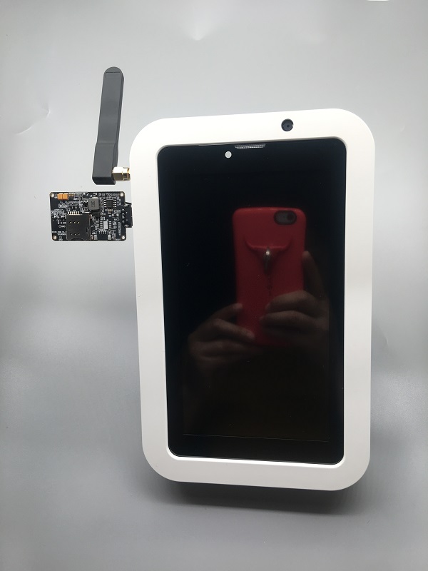
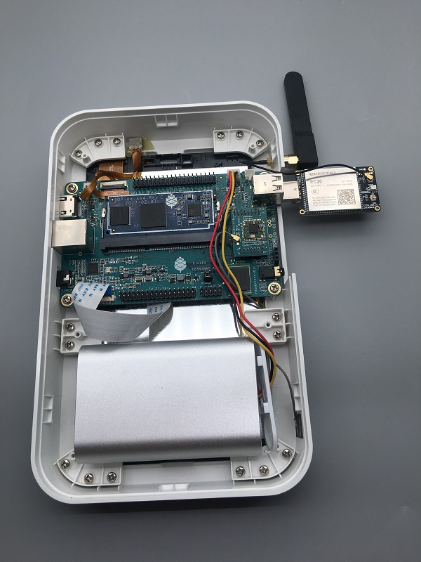
Accessories Step-by-Step Guides
Under ‘Guides for PINE A64(+) accessories’ you can find instructions and guides concerning:
- Playbox Enclosure
- Bluetooth and WiFi module
- 7" Touch Screen LCD Panel
SoC and Memory Specification
- Based on Allwinner A64/R18
- R18 and A64 are identical SoC but R18 committed for 10 years supply by vendor.
CPU Architecture
- Quad-core ARM Cortex-A53 Processor@1152Mhz
- A power-efficient ARM v8 architecture
- 64 and 32bit execution states for scalable high performance
- Support NEON Advanced SIMD (Single Instruction Multiple Data) instruction for acceleration of media and signal processing function
- Support Large Physical Address Extensions(LPAE)
- VFPv4 Floating Point Unit
- 32KB L1 Instruction cache and 32KB L1 Data cache
- 512KB L2 cache
GPU Architecture
- ARM Mali400MP2 Dual-core GPU
- Support OpenGL ES 2.0 and OpenVG 1.1 standard
System Memory
- RAM Memory Variants: 2GB LPDDR3.
- Storage Memory: SPI Flash and optional eMMC module from 16GB up to 64GB
Project Anakin, SOPine Module and Baseboard Information, Schematics, and Certifications
- Model “A” Baseoard Dimensions: 133mm x 80mm x 19mm
- Input Power: DC 5V @ 2A, 3.7V Li-Ion battery connector, 3.5OD/1.35ID Barrel DC Jack connector, Euler connector
- PINE A64 Connector Layout @courtesy of norm24
- PINE A64 Connector List
- SOPine Module Pin Assignment ver 1.0
- PINE A64 Pi-2/Eular/Ext Bus/Wifi Bus Connector Pin Assignment (Updated 15/Feb/2016)
- Good documentation about PINE A64, A64+, and A64-LTS GPIO pins article
SOPine Module Schematic:
SOPine Model “A” Baseboard Schematic and PCB Board Resource:
- SOPine model “A” Baseboard is an hardware open source project but is not “OSH” compliant
- SOPine Model “A” Baseboard Schematic capture Rev B DSN source file
- SOPine Model “A” Baseboard Schematic Rev B PDF file
- SOPine Model “A” Baseboard PCB Job source file
- SOPine Model “A” Baseboard PCB Gerber file
- SOPine Model “A” Baseboard PCB Layout PDF file
SOPine (together with model “A” baseboard) Certification:
- SOPine with model “A” baseboard FCC Certificate
- SOPine with model “A” baseboard CE Certificate
- SOPine with model “A” baseboard RoHS Certificate
Datasheets for Components and Peripherals
Allwinner A64/R18 SoC information:
- R18 and A64 are identical SoC but R18 committed for 10 years supply by vendor.
- Allwinner A64 SoC Brief Introduction
- Allwinner R18 SoC Brief Introduction
- Allwinner A64/R18 SoC Data Sheet V1.1 (Official Released Version)
- Allwinner A64/R18 SoC User Manual V1.0 (Official Release Version)
X-Powers AXP803 PMU (Power Management Unit) information:
LPDDR3 information:
eMMC information:
- PINE64 eMMC module schematic
- PINE64 USB adapter for eMMC module V2 schematic
- PINE64 USB adapter for eMMC module PCB in JPEG
- SanDisk eMMC Datasheet
- Hynix eMMC Datasheet
- Foresee eMMC Datasheet
SPI NOR Flash information:
Project Anakin module/component related information
5MPixel Rear CMOS Camera module information:
- PINE64 YL-PINE64-4EC 5M Pixel CMOS Image Sensor Module (Description in Chinese)
- S5K4EC 5MP CMOS Image Sensor SoC Module Datasheet
- S5K4EC 5MP CMOS Image Sensor SoC Chip Datasheet
- S5K4EC 5MP CMOS Image Sensor Driver Source Code in C language
LCD Touch Screen Panel information:
- 7.0" 1200x600 TFT-LCD Panel Specification
- Touch Panel Specification
- GOODiX GT911 5-Point Capacitive Touch Controller Datasheet
Ethernet PHY information:
- Realtek RTL8211 10/100/1000M Ethernet Transceiver for PINE A64+ Board
- Realtek RTL8201 10/100M Ethernet Transceiver for PINE A64 Board
Wifi/BT module information:
Enclosure information:
Connector information:
- 2.0mm PH Type connector specification use in Lithium Battery (VBAT) port and RTC Battery port
- 0.5mm Pitch cover type FPC connector specification use in DSI port, TP port and CSI port
right
LTE module information:
- Note: The current Project Anakin kit deploy on using Quectel EC20_R2.1 which belongs to EC25 family. Actual production will use EC25 and EG25-G (still preliminary) module pending on region.
- Quectel EC20 R2.1 LTE Module Specification
- Quectel EC25 LTE Module Specification
- Quectel EG25-G LTE Module Specification
- Quectel EC25 LTE Module AT Cammands Set Manual
- Quectel EC25 LTE Module Hardware Design Guide
- Quectel EC25 LTE Module Reference Design Guide
Other Resources
- Linux Sunxi Wiki page on PINE A64
- Linux Image created by Andre Przywara
- PINE64 Linux build scripts, tools and instructions by Longsleep
- PINE64 Linux image by Longsleep
- Shrinking images on Linux by FrozenCow
- Quectel EC-25 LTE module open source information
Project Don’t be evil
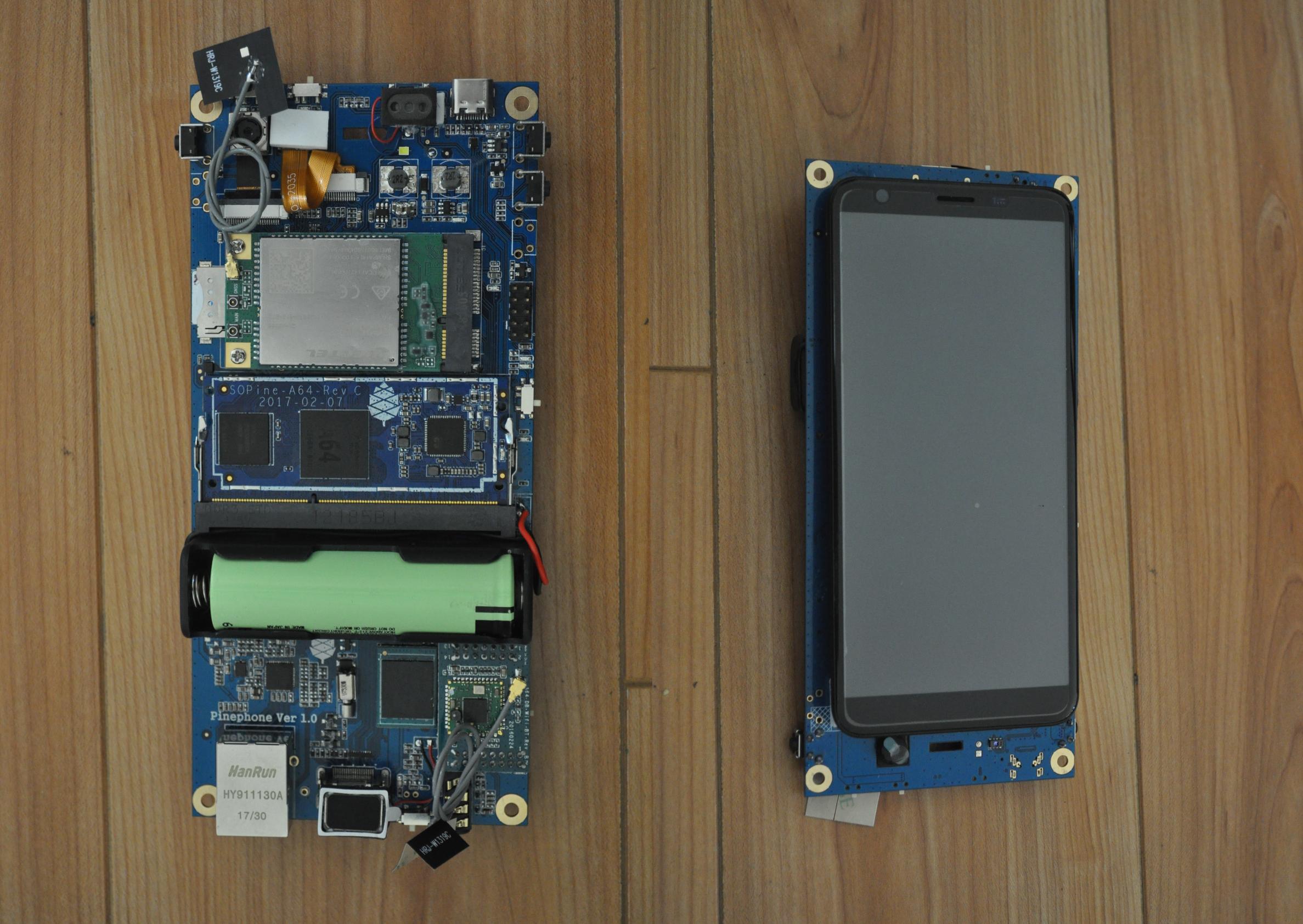
The Project Don’t be evil is the phase two of PINE64’s smartphone, the PinePhone Development Kit. Project Don’t be evil is an actual smartphone developer kit for the PINE64 Smartphone dubbed “PinePhone”. It is used in the early stages of development as a starting point for affiliated projects.
The PinePhone development has been broken down into three distinct phases:
- First phase - Project Anakin
- Second phase - purpose-built development kit code named “Don’t be evil” and introduced at FOSDEM 2019
- Lastly, the third phase which is the PinePhone itself - scheduled to be prototype released in Q3 2019 and BTO batch released with mobile OS parents in Q4 2019 (pending on software development).
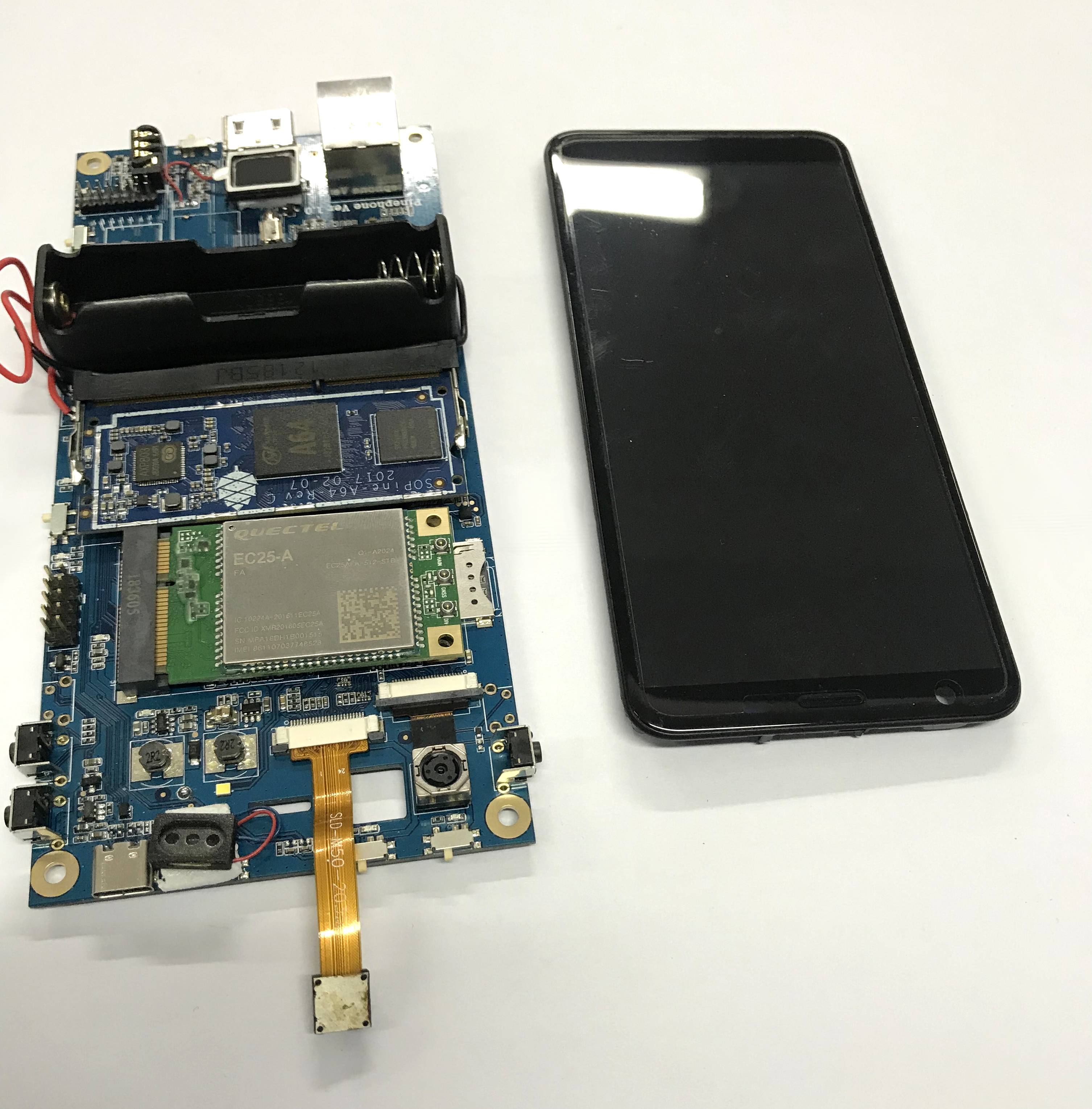
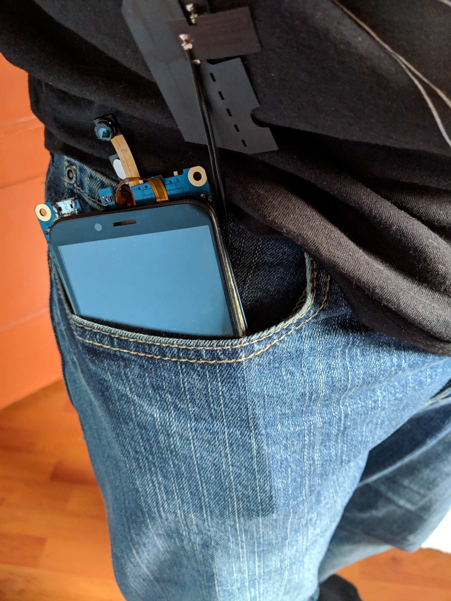
Baseboard and SOPine Module Information, and Schematics
- Baseboard Dimensions: 165mm x 76mm x 19.5mm
- Input Power: DC 5V @ 2A, 3.7V Li-Ion battery connector, USB type-C connector
Baseboard Schematic:
- “Don’t Be Evil” PinePhone Dev kit Baseboard Structure
- “Don’t Be Evil” PinePhone Dev kit Baseboard Ver 1.1 Schematic
- “Don’t Be Evil” PinePhone Dev kit Baseboard Ver 1.1 PCB Artwork
- “Don’t Be Evil” PinePhone Dev kit Baseboard Ver 1.2 Schematic
- “Don’t Be Evil” PinePhone Dev kit Baseboard Ver 1.2 PCB Artwork
SOPine Module Schematic:
Wifi/BT module information:
Pin assignment:
SoC and Memory Specification
Based on the Allwinner A64/R18. The R18 and A64 are identical SoC but R18 committed for 10 years supply by vendor.
CPU Architecture
- Quad-core ARM Cortex-A53 Processor@1152Mhz
- A power-efficient ARM v8 architecture
- 64 and 32bit execution states for scalable high performance
- Support NEON Advanced SIMD (Single Instruction Multiple Data) instruction for acceleration of media and signal processing function
- Support Large Physical Address Extensions(LPAE)
- VFPv4 Floating Point Unit
- 32KB L1 Instruction cache and 32KB L1 Data cache
- 512KB L2 cache
GPU Architecture
- ARM Mali400MP2 Dual-core GPU
- Support OpenGL ES 2.0 and OpenVG 1.1 standard
System Memory
- RAM Memory Variants: 2GB LPDDR3.
- Storage Memory: SPI Flash and optional eMMC module from 16GB up to 64GB
Datasheets for Components and Peripherals
Allwinner A64/R18 SoC information:
- Note: the R18 and A64 are identical SoC but the R18 is committed for a 10 years supply by the vendor.
- Allwinner A64 SoC Brief Introduction
- Allwinner R18 SoC Brief Introduction
- Allwinner A64/R18 SoC Data Sheet V1.1 (Official Released Version)
- Allwinner A64/R18 SoC User Manual V1.0 (Official Release Version)
X-Powers AXP803 PMU (Power Management Unit) information:
LPDDR3 information:
eMMC information:
- PINE64 eMMC module schematic
- PINE64 USB adapter for eMMC module V2 schematic
- PINE64 USB adapter for eMMC module PCB in JPEG
- SanDisk eMMC Datasheet
- Hynix eMMC Datasheet
- Foresee eMMC Datasheet
SPI NOR Flash information:
Related datasheets
2MPixel front CMOS Camera module information:
- 2MP CMOS Image Sensor Module Drawing
- GalaxyCore GC2035 2MP CMOS Image Sensor Product Brief
- GalaxyCore GC2035 2MP CMOS Image Sensor Datasheet
5MPixel Rear CMOS Camera module information:
- 5MP CMOS Image Sensor Module Drawing
- OmniVision OV5640 5MP CMOS Image Sensor Datasheet
- OmniVision OV5640 5MP CMOS Image Sensor Software Application Note
LCD Touch Screen Panel information:
- 5.7" 1440x720 IPS LCD Panel Specification
- fiti JD9365D LCD Controller Datasheet
- 5.7" Front Panel Touch Screen Specification
- FocalTech FT6336GU Front Panel Touch Screen Specification
Lithium Battery information:
Ethernet PHY information:
Wifi/BT module information:
LTE module information:
- Quectel EC25 LTE Module Specification
- Quectel EG25-G LTE Module Specification
- Quectel EC25 LTE Module AT Cammands Set Manual
- Quectel EC25 LTE Module Hardware Design Guide
- Quectel EC25 LTE Module Reference Design Guide
Sensors:
- ST LIS3MDL 3-axis Magnetomater Datasheet
- InvenSense MPU-6050 Six-Axis (Gyro + Accelerometer) MEMS Datasheet
- SensorTek STK3335 Ambient Light Sensor and Proximity Sensor
Software releases
Some these OS images labelled as beta or nightly builds which means they are only fit for testing purposes. These images should be used at your own risk and are not fit for normal use.
postmarketOS

Download:
Instructions:
Notes:
- postmarketOS early alpha test build for microSD boot
- for 8GB microSD cards and above
- Suitable for PinePhone “Don’t Be Evil” Dev Kit version 1.1 and version 1.2
- There are two type of LCD panels. For long touch screen cable, please use the build with inverted wording.
Sailfish OS

The Sailfish OS image is build on Gitlab CI, the latest image can be installed using our flashing script written in Bash.
The script downloads the image and bootloader from our CI, extracts everything and burns it onto the SD card.
Instructions:
- Download the flashing script
- Insert a microSD card in your device
- Make the script executable:
chmod +x flash-it.sh - Execute it:
./flash-it.sh - Follow the instructions. Some commands in the script require root permissions (for example: mounting and flashing the SD card).
Notes:
- The script will format and flash the SD card, make sure that you don’t have any important data on the SD card!
Maemo Leste

Download:
Notes:
- Works on dev kit versions 1.1 and 1.2
- Write the image to a micro SD (8GB+) or eMMC
LuneOS

Download:
Notes:
- It is recommended to use bmaptool
- for example
bmaptool copy https://build.webos-ports.org/luneos-testing/images/pinephone/luneos-dev-image-pinephone-testing-0-15.rootfs.wic.gz /dev/mmcblk0
Mali Driver
For the Mali driver see Mali Driver.
Errata for ver1.1 and ver1.2 board
- Please DON’T insert micro SIM card to dev kit board micro SIM card slot, the SIM data, VPP, and GND signal have been misplaced. A miciPCIe adapter with sim card holder 9shown as below photo) will be provide to developers to correct this mistake.
- The PinePhone dev kit doesn’t charge due to VBUS on SOPine module is not connected. Please connect R9688 solder pads with 0 ohm resistor or using thin wire bridge up the solder pads. Location shows as below:
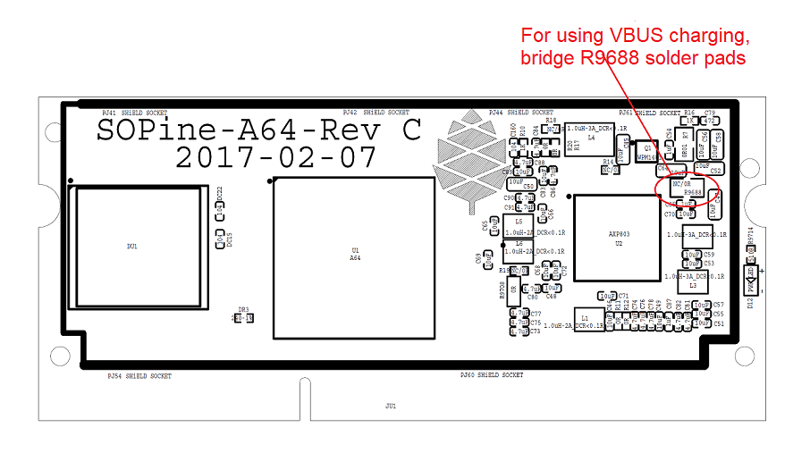
- The SOPINE’s SPI NOR flash storage and the devkit’s camera flash (heh) share the same GPIO pins. The flash storage may not be used.
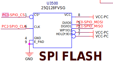
- On the camera flash GPIO conflict, the new assignment of GPIO PB3 pin for SGM3140 FLASH_EN and GPIP PD7 for FLASH_TRIGOUT. Please note that PD7 is also LCD_ID pin which may not be used.
Images:
GPIO_PB3_location Flash GPIOs Reassigned wiring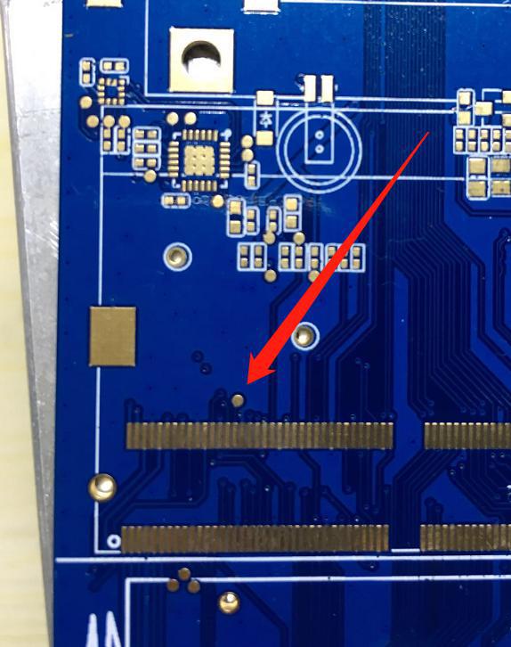
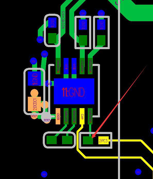
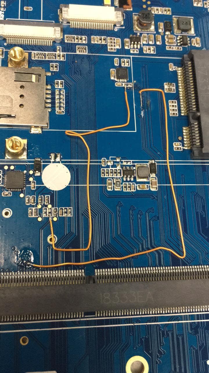
Other Resources
- Linux Sunxi Wiki page on PINE A64
- Linux Image created by Andre Przywara
- PINE64 Linux build scripts, tools and instructions by Longsleep
- PINE64 Linux image by Longsleep
- Shrinking images on Linux by FrozenCow
- Quectel EC-25 LTE module open source information
Accessory
Add-ons
The PinePhone (and PinePhone Pro) is compatible with the official add-on cases, such as the keyboard, the LoRa add-on, the Qi wireless charging add-on and the fingerprint reader add-on. Details can be found under:
USB
The USB-C can be used to power the device, and offers USB2 host and OTG capabilities, and also can make use of the USB-C capability to integrate HDMI signals. Some USB-C hubs are available that offer power throughput, USB connection, an HDMI port and Ethernet connection.
Pogo pins
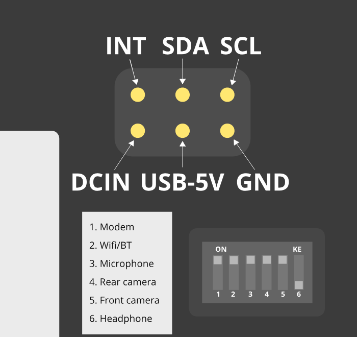
The pogo pins, as visible under the back cover.
The PinePhone has six pogo pins on the back allowing for custom hardware extensions such as wireless charging, an IR blaster, a keyboard extension or extended battery case. The pogo pins provide access to an interrupt line, power inputs/outputs and an I2C interface.
| Interrupt | SDA | SCL |
| DCIN | USB-5V | GND |
DCIN and USB-5V are the names used in the schematics. The actual behavior of these pogo pins is not obvious based on their names. DCIN is connected both to the VBUS line of the USB Type-C connector and to the ACIN/VBUS inputs on the PMIC. This means that, depending on a number of factors, DCIN may be at 0 V or 5 V. USB-5V is connected at the output of an LP6226 DC/DC boost converter (5 V), which in turn is fed by the PS output of the PMIC. The boost converter is enabled or disabled by a GPIO output from the A64 SoC, controlled by software (e.g. the Linux kernel). Depending on inputs and decision made by the PMIC, PS may be at the battery voltage (fed “directly” by the battery through a transistor controlled by the PMIC), or at the “USB” voltage (fed by the PMIC’s ACIN/VBUS inputs). This means that depending on a number of factors, USB-5V may be at battery voltage (between 3.0 V and 4.3 V), or at 5 V.
Because the PinePhone may act as a USB host (providing 5 V at the USB Type-C connector’s VBUS to a connected device) or as a USB device (drawing from a 5 V source on the USB Type-C connector’s VBUS), DCIN is actually not strictly an input nor an output. Some community analysis of the PinePhone schematic (and some testing) indicates that you can connect a 5 V power supply to DCIN in order to power the phone at the PMIC’s ACIN/VBUS inputs (and, as a side effect, charge the battery). This may not be safe to do in all conditions, e.g., when the phone is acting as a USB host to a connected USB device. It should also be safe to use DCIN as a power output from the PinePhone, e.g., when a USB Type-C charger is connected, you can draw current directly from the USB Type-C port’s VBUS, which is provided by the charger. Please note that, when using DCIN as an output from the PinePhone, DCIN isn’t “always on”; it may be 0 V. It is currently not documented on how much current can be safely drawn.
USB-5V should be safe to use as an “always on” power output from the PinePhone. Depending on a number of factors, voltage may be from 3 V to 5 V; thus, if you are using USB-5V to power your pogo-pins expansion board, you will probably need to use DC/DC converters/regulators as appropriate. USB-5V is on even while the A64 SoC is powered down.
The I2C and interrupt lines have pull-ups on the phone side. The I2C lines are pulled up to 3v3 by the phone.
For a breakout board see here. For an example project see Martijn’s blog post “Making a backcover extension for the PinePhone”.
PINE64 store currently sells the PinePhone Flex Breakout Board. With the pitch being 2.54 mm, this Flex Breakout Board may have leads soldered directly to the contacts for use in a solderless board. A non-soldered solution would be to use a TE AMP Connector that will accept a Flat Flexible Cable 2.54 mm pitch.
Back cover
A step file for the back cover for creating custom cases is freely available here.
Serial console
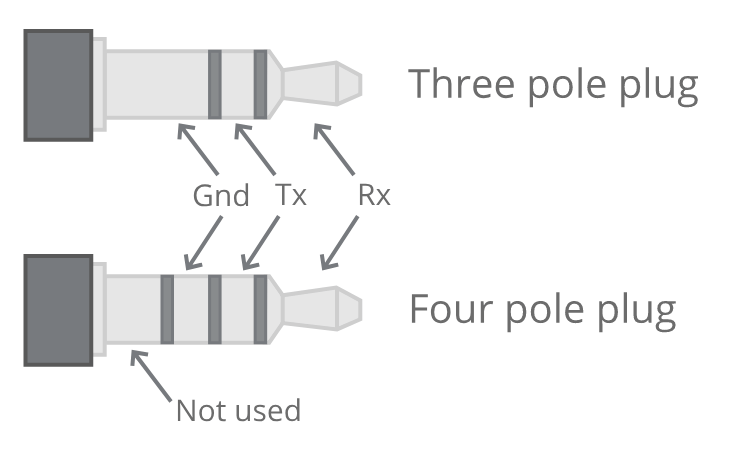
Pinout of the serial adapter.
The PinePhone has a serial port in the headphone connector, it’s activated by the 6th contact on the dipswitch. If the switch is set to “on”, the headphone connector is in audio mode, if it is set to “off” it’s in UART mode. The UART serial connection can also be used for communication with other devices from the PinePhone.
The UART is 115200n8.
The pinout for the serial connector is:
- Tip: RX
- Ring: TX
- Sleeve: GND
You can buy a serial debug cable from the PINE64 Store. The store cable uses a 4 ring plug, as seen in the here, but a 3 ring plug works just as well. The cable uses a CH340 chipset based serial to USB converter, but any 3.3v serial connection can be used. Because it is a “host”/DTE it means that you need a cross modem cable (Null Modem) with TX on Tip to be connected to RX. A cable like e.g. FTDI TTL-232R-3V3-AJ which has TX on Tip and RX on Ring fits perfectly.
Battery
The phone ships with a protective plastic sticker between the battery and the phone to protect the device from turning on during shipping. You need to gently open the back cover, then remove the battery and finally remove the sticker and check that the pins aren’t bent. Note: If the battery is stuck inside the phone, the mid screw in the lower part of the midframe needs to be slightly loosened, see here.
The supplied battery is meant to be compatible with Samsung part number EB-BJ700BBC / BBE / CBE from the 2015 J7 phone. The extended life aftermarket BBU does fit, although it is a tight fit.
The battery terminals, from the nearest to the battery edge to the nearest to the middle of battery, are as follows:
| +ve | thermistor | -ve | not connected |
The battery includes a protection circuit that isolates it in a number of fault conditions, including if it is discharged too far. The fully discharged battery can be recharged by connecting the phone to a charger with a sufficient output. Once it has charged sufficiently you will be able to boot the phone.
Camera
The PinePhone has two cameras, OmniVision OV5640 with 5MP (up to 2592 x 1944 pixels) as rear camera and GalaxyCore GC2145 with 2MP (up to 1600 x 1200 pixels) as front camera.

Example picture taken on the PinePhone’s rear camera by Martijn Braam using his app Megapixels.
Further details regarding the camera and the Megapixels camera app can be found on Martijn’s blog.
FAQ
A list of frequently asked question.
Hardware
Revisions
What are Community Editions?
Community Editions of the PinePhone were versions of the PinePhone which came preinstalled with the operating system of a partner project and featured the logo of the project on the back panel. The Community Edition was intended to help partner projects developing these systems: “Community editions are meant to bring exposure to partner-projects operating systems and communities, as well as help finance ongoing development.”, source.
Is the Community Edition hardware the latest revision?
The Community Edition program (featuring the mainboard numbers 1.2 through 1.2b and branded back covers) which provided the branded PinePhones has since ended, and a Beta Edition has since been released. The only difference between each Community Edition is the inclusion of crucial bug fixes, with the last issue being fixed with the 1.2b motherboard shipping with the Manjaro CE PinePhones. The 1.2b motherboard is also currently used in the Beta Edition PinePhones, however the Beta Edition units do not ship with any back cover branding. There are currently no plans for further hardware revisions.
Aside from the back cover, the only other difference between each Community Edition is that starting with the postmarketOS PinePhone, a convergence package option was released that adds another gigabyte of ram to the phone and a 32GB eMMC instead of a 16GB eMMC. Convergence packages also included a dock for plugging in USB peripherals and connecting to an HDMI monitor, however you can purchase a generic USB-C dock to use with a 2GB PinePhone.
The predecessor to the Convergence Edition PinePhones was the Braveheart Edition intended for developers to bring up the platform, which had the version number 1.1. For more details about the topic see PinePhone.
Will there be other Community Editions?
Five Community Editions have been announced: UBports, postmarketOS, Manjaro, KDE, and Mobian. Since the release of the Mobian edition, the Beta Edition PinePhones have been released and the Community Edition Program has ended.
In simple terms, what are the differences between Braveheart and the new Community Edition?
The Braveheart PinePhone was the first public revision of the PinePhone which was intended solely for developers and Linux enthusiasts. The UBports Community Edition was the next revision of the PinePhone with an updated mainboard based on feedback from the Braveheart Edition, see PinePhone. All current revisions of the PinePhone continue to be intended for developers and enthusiasts, however, PINE64 will be starting to offer partnered retail units of the PinePhone which will have a better warranty and technical support (keep in mind even then it is not intended for a broader audience at this time, as the software still needs work and the hardware does not hold up well to modern consumer standards).
Will there be a newer revision after the Community Editions?
Starting with the UBports Community Edition the PinePhone has gotten CE and FCC certifications, repeating the certification process due to changes in the hardware design is very expensive, so the 1.2b motherboard is viewed as the final revision. The PinePhone (and parts for them) will be produced and sold for at least 5 years.
Will there be hardware differences between the Community Editions?
Besides the varied back covers, starting with the launch of the PostmarketOS CE there has been the release of a convergence package option for the PinePhone which includes more ram and storage, and an included dock for convenience. There has also been minor hardware changes with the UBports CE (mainboard 1.2) and the Manjaro CE (mainboard revision 1.2b).
General
How powerful is the PinePhone’s hardware?
The PinePhone is about on par with a Raspberry Pi 3 in terms of CPU performance, however it’s Mali 400 MP2 is much weaker than the Pi 3’s VideoCore IV. The Mali 400 was the first mobile OpenGL ES 2.0 GPU on the market back in 2008 when it was released, compared to the much newer Videocore IV released in 2010. The PinePhone has been shown to handle smooth H.264 1440p30 video playback using Cedrus and gstreamer as documented here. The device should be more than capable of a smooth phone experience when used in conjunction with well optimized software that makes use of its hardware features. It is also capable of running many light games (including 3D ones such as SuperTuxKart), and retro gaming. Expect further speed improvements over time as the drivers are improved, and in the meanwhile you can look into slightly Overclocking the device (at your own risk).
Sound
The default ringtone for Mobian Phosh can be found at /usr/share/sounds/freedesktop/stereo/phone-incoming-call.oga
Bluetooth
For some reason, using pipewire-pulse with bluetooth headphones (In my case, Sony WH1000X-M3) using the default LDAC codec causes the headphones to constantly connect and disconnect until they eventually give up pairing. A work around I’ve found is to quickly go into Sound settings and switch the codec to “SBC”.
Modem
The modem isn’t working
In order to use the modem and Wi-Fi/Bluetooth, you need to ensure the battery is inside the device and has a sufficient charge. Even when supplying the phone with enough power, the modem and Wi-Fi chip will not work without a connected battery. Further, double check that you have not put the SD card into the sim card slot, or vice versa.
Does the PinePhone only wake up from sleep for calls and texts?
Yes. Unless the PinePhone is configured to wake up every few minutes from deep sleep in Crust (At the cost of battery life. However, in the future there may be other solutions), then there is not any way to get any notifications for applications. The modem on the PinePhone will wake the device for incoming calls and texts however, and the real-time clock is also capable of waking the device for alarms.
Battery
The battery is stuck inside the phone
The battery can be stuck in the phone if the screws of the frame are overtightened.
First, try loosening the screws to the left and right of the battery compartment and remove the battery, it should go much easier now. These screws may be the culprit as they seem to make the sides of the midframe grip the battery. Do not tighten them fully and the problem should go away.
If your battery is still stuck inside the PinePhone, completely unscrew all the screws of the midframe. Then pull out the battery (you may have to fully take off the midframe in some cases to get it out). And then rescrew the midframe, but only tighten the screws to the point where they are just barely tight to hold. This should allow you to remove the battery easily.
The battery is discharging while the phone is powered off (Braveheart Edition)
The issue is not present on the Community Edition. Due to a hardware bug, after power off, the phone still consumes 20–30mA which drains the battery in 3-4 days. A manual procedure to fix the hardware bug is described here.
The battery only charges to ~84%
Some pre-made operating systems using megi’s kernel limit the maximum amount of charge to roughly ~84% in the hope of prolonging the battery life, as repeatedly reaching the upper level of battery charge reduces the battery’s lifetime (this is not a safety feature!). The same effect however also applies when repeatedly draining the battery to a low level - users are therefore advised to consider if that setting is reasonable depending on their usage. The setting can be overwritten via Sysfs, to let the battery fully charge (this can lower the replaceable battery’s lifetime considerably depending on the charging behavior!):
echo 4350000 > /sys/class/power_supply/axp20x-battery/voltage_max_design
Privacy Switches
What are the privacy switches doing?
| Number | Name | Explanation | Description |
|---|---|---|---|
| 1 | Modem | Pulls Q1501 gate up (FET disabling modem power) | “On” enables cellular communication and GNSS hardware, “off” disables it. |
| 2 | Wi-Fi / Bluetooth | Pulls up CHIP_EN | “On” enables Wi-Fi and Bluetooth communication hardware, “off” disables it. |
| 3 | Microphone | Breaks microphone bias voltage from the SoC | “On” enables audio input from on-board microphones (not 3.5mm jack), “off” disables it. |
| 4 | Rear camera | Pulls up PWDN on OV5640 | “On” enables the rear camera, “off” disables it. |
| 5 | Front camera | Pulls up PWDN on GC2145 | “On” enables the front camera, “off” disables it. |
| 6 | Headphone | Pulls up IN2 on analog switch BCT4717ETB | “On” enables audio input and output via the 3.5mm audio jack, “off” switches the jack to hardware UART mode. |
Memory
What’s the speed difference between the eMMC and SD cards?
Maximum transfer speed of the eMMC is around 85 MB/s, while SD cards are limited to approximately 23 MB/s (even with faster cards).
GPS
GPS doesn’t work
Like almost all smartphones, the PinePhone GPS antenna is small and can only get a first fix unassisted if the GPS signal is very strong. To make first fix faster and more reliable, phones download assistance data either from the phone network or from the internet. The GPS in the PinePhone modem supports the internet based assistance method, as detailed in the modem documentation, but this is currently only supported by a few distributions, and a proof of concept script that shows it can work.
Until aGPS support becomes standard you’ll have to make some manual changes - see for example Mobian wiki
GPS can’t determine direction
Currently, due to the magnetometer not being hooked up in software at this time, it is not possible for GPS software to use the phone’s compass functionality. This means while you are walking it will not be possible to determine the direction of travel. This is not as much of an issue for vehicles as the faster speeds mean that it is possible to estimate the direction of travel, however it will still be an issue should the vehicle travel through a tunnel and lose GPS signal.
Software
Installation
How can I install an operating system on the SD card / eMMC?
See Installation instructions.
Booting
What’s the boot order for SD cards and eMMC?
The PinePhone will automatically boot from microSD if a bootable card is inserted. If no (bootable) microSD is found, it will boot from eMMC.
How can I select different operating systems at boot?
There was a project by Danct12 which allowed the user to select different operating systems at boot, but the repository has since been archived: https://github.com/dreemurrs-embedded/Pineloader.
I turned on my Manjaro CE PinePhone. The red LED and screen backlight are briefly lit, then both are not and it will not boot.
This can be the result of at least one situation:
- The eMMC installation became corrupt or otherwise unbootable
- An SD card is present but not bootable (consider PinePhone Troubleshooting)
If there is an installation of Manjaro on both the eMMC & an SD card, the SD card will always boot first on the device. Try taking the SD card out and booting the installation that is on the eMMC. If the problem persists, it is likely there is an issue with both installations and you will need to reinstall your distribution. You may also want to check with your distribution’s maintainers if boot issues are a common problem in a recent update.
I did not install an update in Ubuntu Touch and I’m stuck on the PINE64 logo after rebooting.
- Use a USB A-C cable to plug your phone into your PC
- Hold the PinePhone’s power button for 4 seconds or more to power it off.
- Wait 5 seconds
- Hold the Volume Up and Power buttons on the PinePhone to boot into recovery. You should see the LED light red, then yellow, then green. The “Installing update” screen will appear, but a progress bar to indicate update progress will not. Ignore the “Installing update” part.
- Your PC may automatically mount the PinePhone’s partitions. If it does, Safely Remove or Eject all of them.
- Open a terminal on your PC. Type
telnet 172.16.42.1 - You should receive the text ‘Welcome to Rescue SD Shell|’
- In the new Rescue SD shell, type
umount /dev/mmcblk2p10; e2fsck -fy /dev/mmcblk2p10 && sync - Once this command pipeline finishes, type
sync && reboot -f
Your PinePhone should reboot into Ubuntu Touch. Now head to Settings - Updates and install the new update!
If these steps did not solve your issue, please create a new thread here on the PINE64 forums, note what the problem looks like, then say that you’ve tried these steps already.
This is caused by corruption on the userdata partition. Normally this should be fixed by ’e2fsck’ in the initramfs, however, an error in image creation means that that version of e2fsck is unable to correct the corruption. This has been fixed in all new PinePhone updates, so if you update from the factory image to any other image available to the PinePhone now, you will not experience this issue any longer.
The PinePhone does not boot
Most operating systems on the PinePhone do not boot if the battery is not connected or if it is fully drained. If you received a new PinePhone make sure to remove the battery isolator as explained under PinePhone Getting started.
If you removed the battery isolator and the battery contacts are intact, the battery is either fully drained or there is no valid OS (or a corrupted OS or bootloader) installed on the eMMC or the SD card. Make sure to charge the phone with a compatible charger (500 mAh is not enough for modern phones), as well as the installation instruction under Installation instructions. If the OS got corrupted it is highly recommend to simply reflash.
If nothing works please don’t hesitate to contact the community, they are eager to help and booting issues are usually very easy to solve (as they are typically either battery or installation related). The phones itself are all tested individually at the factory. Do not contact PINE64’s support for booting issues.
A protection foil isolates the battery for the shipping. The microSD belongs in the upper slot, the micro SIM in the lower slot.
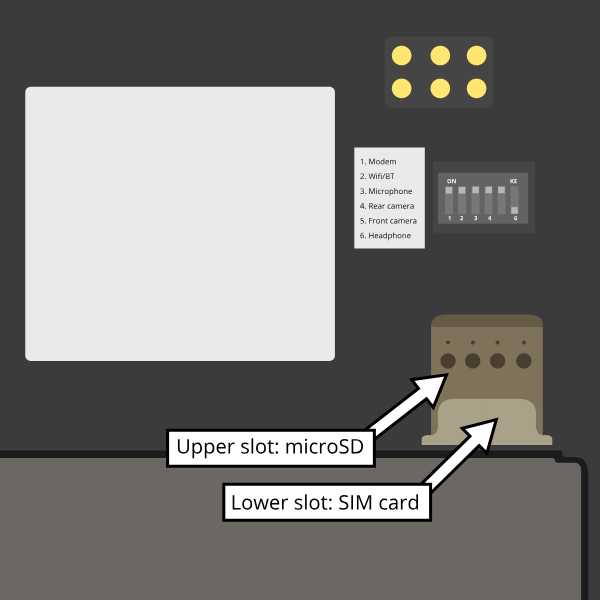
Can I install a different OS on my Community Edition?
Yes. While all the Community Edition PinePhones come with an OS preinstalled, you are free to use any OS on the integrated storage (the eMMC) or an SD card, see Installation instructions and Operating systems on how to install them.
Other
How can I enable SSH?
In Ubuntu Touch you can run “sudo start ssh” to get a one-time start, or edit /etc/init/ssh.override and remove the manual line to make it auto-start.
In other distributions you may have to install SSH through its package manager and then proceed to use its init system to enable it. For Manjaro, Arch, and Mobian you can use “systemctl enable sshd” and “systemctl start sshd” command to enable and start the ssh daemon.
What works, what doesn’t?
For Ubuntu Touch see https://gitlab.com/ubports/community-ports/pinephone#what-works-what-doesnt.
Other distributions will have different levels of functionality. Please refer to the release page of your chosen distribution for further information.
I can’t connect to a 2.4Ghz Wi-Fi network in Ubuntu Touch.
Reboot your device by holding the power button until the “Power” dialog appears, then pressing “Restart”.
If that does not fix the issue, note that all the following conditions must be met to use Wi-Fi on the PinePhone:
- The plastic tab between the battery and the device’s battery contacts has been removed
- The battery is installed
- The Wi-Fi privacy switch (switch number two) on the rear of the device is switched “ON”
Wi-Fi in the PinePhone only seems stable after a warm reboot like this.
What’s the status of Android for the PinePhone?
Currently, there isn’t any major push to get Android running well on the PinePhone. The developer Icenowy did get a partially working Android image, but it was slow and buggy, lacking some major functions. As of now, use Anbox as an alternative for your android apps, which is currently not included in Ubuntu Touch. In other distributions your millage may vary on what applications will run and how well.
Why are my apps loading slower than on my Android phone?
Android has multiple techniques in place to speed up launching applications after the first launch, such as the “Dalvik cache”.
Using an alternative filesystem such as F2FS on the eMMC (which is considerably faster than running software on the SD card) may help improve performance slightly. Over time you can expect further optimizations and improvements in various distributions that will help speed up the PinePhone.
How can I turn on the backlight?
On some devices the default calibration of the backlight is not sufficient and the minimum setting of the brightness of the used OS can be too low, causing the backlight to completely shut down. In that case it is recommended to connect the phone to a charger and/or to shine a flashlight at the screen to adjust the brightness to a higher setting again.
On many Linux distributions the brightness setting is an integer between 0 and 1000 and available at runtime in /sys/class/backlight/backlight/brightness and stored at shutdown and loaded at boot from /var/lib/systemd/backlight/platform-backlight:backlight:backlight by systemd-backlight@backlight:backlight.service. Changing the brightness setting can be done at runtime, for example over SSH, by executing as root echo 500 > /sys/class/backlight/backlight/brightness. The stored brightness setting can be modified using another system, by mounting the root filesystem of the system you want to fix and by executing echo 500 > [MOUNT LOCATION]/var/lib/systemd/backlight/platform-backlight\:backlight\:backlight.
How can I contribute regarding the WiFi and Bluetooth firmware?
The PinePhone uses Realtek RTL8723CS for its Wi-Fi and Bluetooth connectivity. Unfortunately, just like the other Realtek wireless chipsets (see more info) - the RTL8723CS chipset requires proprietary firmware for Wi-Fi and Bluetooth functionality. For those who want to create replacement free software firmware, resources like this and this (different chipsets, but still Realtek) could be a great starting point for further research.
SMS
The phone does not receive SMS
Sometimes incoming SMS messages are not being received, but outgoing ones, phone calls and data are working fine. One cause of this is if ModemManager fails to receive messages from the modem and they build up. These messages are not cleared by either rebooting reflashing the phone.
New versions of the (mostly) foss community firmware implement a workaround that helps ModemManager receive stuck messages.
Most UIs (at least phosh, plasma, and sxmo) use ModemManager to communicate with the modem including for phone calls, cellular data, GPS and SMS.
You can check for stuck sms messages using the mmcli command:
$ mmcli -m any --messaging-list-sms Found 10 SMS messages: /org/freedesktop/ModemManager1/SMS/0 (received)
Any messages that are listed have gotten stuck, they can be deleted like this:
$ mmcli -m any --messaging-delete-sms=77 (Repeat with all listed messages)
For more information on the messaging related actions available in mmcli you can check the help with mmcli --help-messaging. This article is also helpful in learning: https://electronproton.com/mmcli-command-examples/.
Shipping
I did not receive an order confirmation
Check your “spam” folder. It was reported that some users did not receive an order confirmation. You will also still get a shipping notification when the device ships out, even if you didn’t get an order confirmation email.
When does the phone ship?
For up-to-date information when the phone’s shipping date is estimated, see the edits in the corresponding forum thread.
It is shipping day but I did not receive a shipping notification
For shipments with DHL the shipping notification is sent out as soon as the packet reached DHL’s warehouse and scanned (it can take up to 24 hours after scanning after the shipment is added to DHL’s database). For all other shipments (via Ascendia) the notification is sent out sometime after shipment.
When does my phone ship if I order now?
Orders made after Friday, 22nd May 2020 are shipped after the first bulk of pre-orders has been shipped. The exact date is not known yet due to various reasons, it may be a few weeks after the first bulk shipped. The forum will be edited with updated information and you will receive a shipping notification when the device was shipped.
What about import taxes?
Import taxes have to be paid by the buyer depending on the jurisdiction of the country of the buyer. Please check with your local laws if there are import taxes to pay and if so how to do the tax filing.
Accessories
Protection
Which screen protector should I use?
Protecting your screen is important, especially for devices like the PinePhone that doesn’t have access to the newest glass technology. The Braveheart and Community Editions of the PinePhone comes with a plastic film screen protector installed, and PINE64 sells a tempered glass screen protector in their store.
You can also buy a third-party screen protector, as the screen protectors for the iPhone 11 Pro Max/XS Max fit the PinePhone pretty well based on this forum post.
Batteries
I want a replacement battery, which one should I buy?
Replacement batteries for US customers are available in the store.
Currently the PinePhone battery is known to be compatible with replacement batteries for the Samsung J700. Specifically, models “EB-BJ700BBC” and “EB-BJ700BBE” are compatible with all PinePhone models, and “EB-BJ700CBE” is compatible with Community Editions after UBPorts (due to plastic tabs on its bottom which only the newer phones have tolerance for).
External hardware
Will PINE64 sell other add-ons made for the PinePhone?
Yes, currently there is a keyboard case with similarities to the Psion 5 which includes an internal battery, and a Qi wireless charging add-on planned, both of which PINE64 intends to directly sell. There is the potential for future add-ons such as a game pad, however that is currently just an idea and not in any way planned.
Further information
Accessibility
Although most accessibility support for the PinePhone and PinePhone Pro is implemented in software, the underlying hardware is still relevant. This page discusses some issues and options.
Input
Braille
Various portable devices, such as Apple’s iPhone, support braille input. This uses multi-touch capability on the device’s capacitative touch screen. The gating factors for this input mode are the dimensions of the screen and the number of contact points that can be distinguished.
The PinePhone screen has 1440 × 720 pixel resolution and measures 5.95" diagonally. Assuming that the pixels are square, the screen dimensions should be about 2.68" by 5.37". This should provide plenty of room for four fingertips on each of the long sides. Indeed, there is a bit of space left over for control functions, etc.
Keyboard
The PinePhone can support either Bluetooth or USB keyboards. So, a device such as the Jelly Comb Foldable Bluetooth Keyboard B003 might be a reasonable input device.
Speech
The PinePhone should be able to accept speech input using either Bluetooth or its built-in microphone. According to this page, Mozilla’s DeepSpeech ASR (automatic speech recognition) engine works pretty well on a Raspberry Pi 4, using only a single core. Assuming that the PinePhone’s more limited (2 or 3 GB) RAM isn’t a constraint, the phone should be able to produce similar results.
Output
Speech
The PinePhone’s processor should have plenty of capacity to generate clear speech. This can be output using either the 3.5 mm audio jack or a Bluetooth connection.
See also
Components
| Component | Model |
|---|---|
| Touchscreen | Goodix GT917S |
| Rear camera | OmniVision OV5640 |
| Camera flash | SGMICRO SGM3140 |
| Front camera | GalaxyCore GC2145 |
| LCD | Xingbangda XBD599 |
| WiFi | Realtek RTL8723CS |
| Bluetooth | Realtek RTL8723CS |
| Modem | Quectel EG25-G |
| GNSS/GPS | Quectel EG25-G |
| Magnetometer | ST LIS3MDL |
| Ambient light / Proximity | SensorTek STK3335 |
| Accelerometer / Gyroscope | InvenSense MPU-6050 |
| Vibration motor | Unknown model |
| Notification LED | LED0603RGB |
| Volume buttons | Buttons connected to the KEYADC |
| Power button | X-Powers AXP803 |
| Battery fuel gauge | X-Powers AXP803 |
Components list
The following list of components are found in the schematic for the PinePhone 1.2b.
Abreviations used in schematic
The following abbreviations are used as the starting letter(s) to identify the components in the PinePhone schematics:
- ANT: antenna
- C: capacitor
- D: diode
- DU: Only used in the “DU1”, which is an integrated circuit for memory
- ED: Zener diode to protect against electrostatic discharge
- FB: ferrite bead
- J: wire link (i.e. a connector)
- R: resistor
- L: inductor
- NC/: not connected (i.e. the part probably isn’t placed on the board, but there are circuits in the PCB for it)
- Q: transistor
- SW: switch
- T: test point
- U: integrated circuit (i.e. a silicon chip)
- X: crystal oscillator (used for clocks)
P.4 LPDDR3 FPGA178
Note: The title of this schematic page should be changed from “LPDDR3 FPGA178” to “LPDDR3 FBGA178”, because the RAM chip is a 178-pin fine pitch ball grid array (FBGA), not a field-programmable gate array (FPGA).
DU1:
- Artmem ATL3A1632H12A 2GB 800MHz LPDDR3-1600 SDRAM, FBGA-178 11.0x11.5x0.93 mm
- Note: RAM will be clocked slower, since the Allwinner A64 only supports up to 3GB DDR3-1333 (666.5MHz) and doesn’t specify the top supported LPDDR3 speed.
P.5 CPU
U1:
- Allwinner A64 1.2Ghz 4x Cortex-A53, 64-bit, superscalar, 32KB instruction & 32KB data L1 cache per core, 512KB L2 shared cache, ARM Mali-400 MP2 (Utgard) GPU, HDMI 1.4 (up to 4K@30), USB 2.0 with OTG, MIPI CSI, 4 channels in/out, 24-bit, 8-48 KHz audio, video encode: H.264 1080p@60, video decode: H.265 4K@30, H.265 1080p@120, H.264, MPEG1/2/4 / VP8 / AVS / AVS+ 1080p@60, FBGA-396 15x15 mm
- Note: Clocked at 1.152Ghz on the PinePhone.
X501:
- Axtal AXX3225 24MHz ±10ppm quartz crystal oscillator in SMD package, 3.2x2.5 mm
D500:
- Will Semiconductor ESD5451X 1-line, bi-directional, transient voltage suppressor, EDS protection up to ±30kV and 8A.
X500:
- Seiko Instruments Inc. (SII) SC32S 32.768KHz crystal oscillator
- Note: Not clear if using the SC32S-12.5PF20PPM or the SC32S-7PF20PPM
P.6 POWER
ED600:
- Will Semiconductor (WILLSEMI) ESD5451X 1-line, bi-directional, transient voltage suppressor, EDS protection up to ±30kV and 8A.
- Note: This part is marked as optional in the schematic and may not be included.
U600:
- X-Powers AXP803 power management integrated circuit (PMIC) optimized for multi-core systems, li-ion battery fuel gauge, USB charger (up to 2.8A), QFN 68-pin, 8x8 mm
Q600:
- Will Semiconductor WPM1481 single P-channel, -12V, -5.5A, power MOSFET
J600:
- BA5924211-R battery connector
- Note: Picture shows this part as having 8 pins, but the schematic shows 6 pins. One page says that it is made by LateralPressure, but another says it is made by ROHM.
L606:
- IND_252010 2.2uH-2A inductor
- Note: Maybe this is the TDK VLS252010HBU.
U601:
- LowPowerSemi LP6226CB6F high efficiency boost DC/DC converter with 33V, 1.5A power MOSFET, SOT23-6 package
D600:
P.7 NAND/eMMC
U700:
- Kimtigo KM110SS0016GxA-DDD00WT 16GB eMMC 5.1 TLC NAND Flash memory, FBGA-153 11.5×13.0×1.0 mm.
- Note 1: The schematic says the package is BGA-169, but the Kimtigo documentation says it is FBGA-153.
- Note 2: The A64 only supports up to eMMC 5.0.
- Note 3: The schematic lists the part as KM110SS0016GxA-DDD00WT, but these photos show that its variant, the KM111SS0016GxA-DDD00WT, is being used in the 16GB PinePhone.
P.8 AUDIO
ED800, ED801, ED802, ED803, ED804, ED805, ED806:
- Will Semiconductor ESD5451X 1-line, bi-directional, transient voltage suppressor, EDS protection up to ±30kV and 8A.
U801:
- Broadchip BCT4717ETB-TR 4.0Ω, 300MHz bandwidth, dual bi-directional SPDT (single-pole/double-throw) analog switch
J800:
- EAROUTN-A64 receiver
J801:
- JA-3606-001AA 3.5mm audio jack
Q801:
- Toshiba SSM3K35MFV field-effect transistor, silicon N-channel MOS type
U800:
- Shanghai awinic technology AW8737SCSR high efficiency (80%), low noise (53μV), ultra-low distortion (0.008%), constant large volume, 7th generation class K audio amplifier, 1.6×1.68 mm CSP-14 package, 0.4mm pitch datasheet
FB800, FB801:
P.9 T-CADD/USB
Q901, Q902, Q903:
- Toshiba SSM3K35MFV field-effect transistor, silicon N-channel MOS type
ED900, ED901, ED902:
- Will Semiconductor ESD5451X 1-line, bi-directional, transient voltage suppressor, EDS protection up to ±30kV and 8A.
J901:
- SA-2202-112 25-pin Micro-SIM and TF slot
P.10 CAMERA
J1000:
- T03-1025-FG01 27-pin connector to the rear camera.
- Note: The schematic says “GC2035-200W”, which is a mistake because the rear camera is the OmniVision OV6540.
J1001:
- T03-1025-FG01 27-pin connector to the front camera.
- Note: The schematic says “GC2035-200W”, which is a mistake because the rear camera is the GalaxyCore GC2145, not the GalaxyCore GC2035.
U1000:
- Shanghai awinic technology AW3641EDNR flash LED driver with programmable timer and PWM dimming torch mode, 1A, 8 current levels.
P.11 LCM/CTP
Note: “LCM/CTP” means “liquid crystal display monitor/capacitive touch panel”. An LCM generally includes an LCD screen + LED backlight + PCB with the LCD controller + frame.
J1100:
- FPC24-PT05B, OK-24F-04 28-pin connector to the MIPI-DSI LCD
LED2:
- RGB LED
J1101:
- CON6-0.5, TP_6PIN-ZQ01 8-pin connector to the capacitive touch panel controller
- Note: The label says that the connector has 6-pins, but the schematic shows 8-pins.
ED1100, ED1101, ED1102, ED1103:
- Will Semiconductor ESD5451X 1-line, bi-directional, transient voltage suppressor, EDS protection up to ±30kV and 8A.
U1100:
- Chipown AP3127B025 step-up DC/DC converter series, white LED backlight driver, 6-pin SOT-23-6L package.
P.12 SENSORS/MT/KEY
J1200:
- 8-pin connector to test points ED1200, ED1201:
- Will Semiconductor ESD5451X 1-line, bi-directional, transient voltage suppressor, EDS protection up to ±30kV and 8A.
U1200:
- STmicroelectronics LIS3MDL ultra-low-power three-axis magnetometer, LGA-12 2.0x2.0x1.0 mm datasheet
- Note: The LIS3MDL is currently unavailable, so it has been replaced in the PinePhone Beta Edition with the Voltafield AF8133L e-Compass, which is unlisted on the Voltafield web site, but the AF8133J is listed. Presumably U1200 will be unpopulated and U1203 will be populated in the Beta Edition, since they appear to be alternatives.
U1201:
- SensorTek https://web.archive.org/web/20190601120915 / STK3311-A proximity and ambient light sensor (large gap) with built-in infrared LED, DFN-8 3.94x2.36x1.35 mm datasheet
U1202:
- TDK InvenSense MPU6050 six-axis, low-power MEMS gyroscope and accelerometer, QFN-24 4x4x0.9 mm datasheet
U1203:
- Asahi Kasei Microdevices (AKM) AK09911 3-axis electronic compass IC with Hall sensor, 8-pin WL-CSP (BGA), 1.2×1.2×0.5 mm
- or Voltafield Technology Corp. (VTC) AF8133J 3-axis electronic compass with proprietary anisotropic magneto resistive (AMR) technology, 8-pin WLCSP 1.2x1.2x0.5 mm
- Note: These parts appear to be alternatives to be used if the LIS3MDL is unavailable, so U1203 was probably unpopulated in BraveHeart and the Community Editions, but will be populated in the Beta Edition.
U1204:
- Bosch Sensortek BMI120 3-axis gyroscope and accelerometer, LGA-14 2.5x3.0x0.83 mm
- Note: Listed as “NC/BMI120”, where “NC” probably means “not connected”, so there may be circuits in the PCB for the part, but it is not placed on the board. This is probably an alternative to the TDK InvenSense MPU6050, in case it isn’t available or costs too much.
Q1200:
- Toshiba SSM3K35MFV field-effect transistor, silicon N-channel MOS type
D1200:
- Torex XBS104S14 Schottky barrier diode, 1A, 40V, SOD-123A package
J1201:
- 2-pin connector to a motor, 1x1.8 mm
- Note: Presumably this is a vibration motor.
P.13 DIGITAL VIDEO
J1300:
- OK-50F-04 40-pin connector
- Note: This part is probably produced by Shenzhen Yaqi Technology Co., which is part of OCN in Taiwan, and uses the Archie brand name.<
U1304:
- Analogix ANX7688 HDMI to USB-C bridge with MUX, converts HDMI 2.0 to DisplayPort Alternate Mode, USB-C Power Delivery (PD), BGA-64.
- Note 1: The schematic lists this part as “ANX7688S”, but it is unclear what the “S” at the end stands for.
- Note 2: xnux.eu provides more info on the ANX7688, including flashing the firmware.
U1300:
- America Techcode Semiconductor TD6817 1.5MHz 2A synchronous step-down regulator dropout, SOT23-5 package
- or Diodes Incorporated AP3406K-ADJTRG1 buck switching regulator IC positive adjustable 0.6V 650mA datasheet
U1302:
- LowPowerSemi LPW5206H USB power loading switch, N-channel MOSFET, SOT23-5 package
U1303:
- Texas Instruments TXB0104YZT 4-bit bidirectional voltage-level translator with automatic direction sensing and ±15-kV ESD protection, 12-pin DSBGA 1.40×1.90 mm
Q1300, Q1301, Q1302, Q1304, Q1305:
- Toshiba SSM3K35MFV field-effect transistor, silicon N-channel MOS type
U1305, U1309:
- Will Semiconductor WS4621C-1X1 2A, 38 mΩ, 290nA quiescent current and 70nA standby current load switch, CSP-4L 1x1 mm.
U1308:
- Shanghai awinic technology AW3632 high efficiency, low profile, fixed 5V output pump power supply, QFN-8 package
X1300:
- Mercury United Electronics X3225 27.000 MHz crystal oscillator
P.14 WIFI+BT
U1400:
- Realtek RTL8723CS 802.11 b/g/n, single-band (2.4 GHz), Bluetooth 4.0, with SDIO for WiFi and UART for Bluetooth, LGA-40 12x12x1.6 mm.
X1400:
- 24Mhz ±10ppm crystal oscillator
D1400:
- SXSEMI AU0511P1 low capacitance ESD protection diode, SOD-882
ANT1400
- Antenna
P.15 MODEM-4G
U1500:
- Quectel EG25-G https://wiki.pine64.org/wiki/File:Quectel_EG25-G_LTE_Standard_Specification_V1.3.pdf GSM/UMTS/LTE cellular modem and GNSS (GPS/Galileo/GLONASS/BeiDou/QZSS, with A-GPS), LGA-144 9.0x32.0x2.4 mm
U1502, 1503, 1504:
- Texas Instruments TXB0104YZT 4-bit bidirectional voltage-level translator with automatic direction sensing and ±15-kV ESD protection, 12-pin DSBGA 1.40×1.90 mm
Q1501, Q1503, Q1504, Q1505:
- Toshiba SSM3K35MFV field-effect transistor, silicon N-channel MOS type
J1500, J1502:
- MRF004-P01A 4-pin connector
Q1500:
- Will Semiconductor WPM1481 single P-channel, -12V, -5.5A, power MOSFET
- Note: The documentation shows 6 pins, but the schematic shows 8 pins.
Component Counts
| Type of component | Main PCB | USB PCB |
|---|---|---|
| Antenna connectors (ANT_xxx_) | 6 | 4 |
| Capacitors (C_xxx_) | 296 | 16 |
| Diodes (D_xxx_) | 5 | 0 |
| Zener diodes (ED_xxx_) | 17 | 0 |
| Ferrite beads (FB_xxx_) | 6 | 0 |
| Wire links / connectors (J_xxx_) | 14 | 4 |
| Resistors (R_xxx_) | 222 | 0 |
| Inductors (L_xxx_) | 15 | 0 |
| Transistors (Q_xxx_) | 16 | 19* |
| Switches (SW_xxx_) | 1 | 0 |
| Test points (T_xxx_) | 27 | 3 |
| Integrated circuits (U/DU_xxx_) | 24† | 2 |
| Crystal oscillators (X_xxx_) | 5 | 0 |
| Total without test points | 627 | 45 |
| Total with test points | 654 | 48 |
Here is how the PinePhone compares with the Librem 5 in terms of components:
| Type of component | Librem 5 main | Librem 5 USB | PinePhone main | PinePhone USB |
|---|---|---|---|---|
| Antenna connectors (ANT_xxx_) | 3 | 2 | 6 | 4 |
| Capacitors (C_xxx_) | 521 | 11 | 296 | 16 |
| Diodes (D/TVS/ED_xxx_) | 59 | 1 | 22 | 0 |
| Connectors (J/CON_xxx_) | 26 | 10 | 14 | 4 |
| Resistors (R/F_xxx_) | 348 | 8 | 222 | 0 |
| Inductors (L/FB_xxx_) | 79 | 7 | 21 | 0 |
| Transistors (Q_xxx_) | 17 | 0 | 16 | 19* |
| Switches (SW_xxx_) | 5 | 0 | 1 | 0 |
| Test points (T/TC/TP/TS/TV_xxx_) | 126 | 4 | 27 | 3 |
| Integrated circuits (U/DU_xxx_) | 65 | 2 | 24† | 2 |
| Crystal oscillators (Y/X_xxx_) | 10 | 0 | 5 | 0 |
| Total without test points | 1133 | 41 | 627 | 45 |
| Total with test points | 1259 | 45 | 654 | 48 |
- 18 parts for the PinePhone USB-C port are labeled as T_xxx_ in the schematic with the image of transistors, but it is possible that these are resistors and capacitors.
† There are 26 U/DU_xxx_ listed in the PinePhone schematic, but the two extra are for an alternative magnetometer (U1200 / U1203) and an alternative gyroscope and accelerometer (U1202 / U1204) which are unpopulated.
Source: Amos Batto
Other components not in the schematics
- SGMICRO SGM3140 500mA buck/boost charge pump LED driver for camera flash and torch, TDFN-10 3x3x0.75 mm
- Note: The PinePhone page lists the SGM3140, but the schematics contain the U1000: awinic AW3641EDNR, so it is unclear why the SGM3140 is needed.
- Goodix GT917S touch controller
- Sitronix ST7703 MIPI LCD driver
- Xingbangda XBD599 5.99″ IPS LCD, 720x1440 pixels, 16.7M colors, hardened glass
Datasheets
Allwinner A64 SoC information:
- Allwinner A64 SoC brief introduction
- Allwinner A64 SoC Data Sheet V1.1 (Official Released Version)
- Allwinner A64 SoC User Manual V1.0 (Official Release Version)
X-Powers AXP803 PMIC (Power Management IC) information:
LPDDR3 (178 Balls) SDRAM:
eMMC information:
CMOS camera module information:
- PinePhone 5M Pixel Real CMOS Image Sensor Module
- OV5640 5MP CMOS Image Sensor SoC for Rear Module datasheet
- OV5640 Embedded Firmware User Guide – VCM AF Module
- PinePhone 2M Pixel Front CMOS Image Sensor Module
- GC2145 2MP CMOS Image Sensor SoC for Front Module datasheet
LCD touch screen panel information:
- 5.99" 1440x720 LCD IPS Panel specification
- ST7703 LCD Controller datasheet
- GOODiX GT917S Capacitive Touch Controller datasheet
Lithium battery information:
- PinePhone Lithium Battery specification
- PinePhone Lithium Battery ZCV curve chart
- PinePhone Lithium Battery 3D onshape drawing
WiFi/BT module information:
LTE module information:
- https://wiki.pine64.org/wiki/File:Quectel_EG25-G_LTE_Standard_Specification_V1.3.pdf
- https://wiki.pine64.org/wiki/File:Quectel_EG25-G_Hardware_Design_V1.4.pdf
- https://wiki.pine64.org/wiki/File:Quectel_EC2x&EG9x&EG2x-G&EM05_Series_AT_Commands_Manual_V2.0.pdf
- https://wiki.pine64.org/wiki/File:Quectel_EC2xEG25-GEG9xEM05_FILE_AT_Commands_Manual_V1.0.pdf
- https://wiki.pine64.org/wiki/File:Quectel_EC2x&EG9x&EG2x-G&EM05_Series_GNSS_Application_Note_V1.3.pdf
Sensors:
- ST LIS3MDL 3-axis Magnetometer Datasheet
- InvenSense MPU-6050 Six-Axis (Gyro + Accelerometer) MEMS datasheet
- SensorTek STK3335 Ambient Light Sensor and Proximity Sensor
Digital video to USB-C bridge:
Case information:
Other components:
- See the Component List
Press
Vector images and pictures of the PinePhone and PinePhone Pro you can freely use for projects and press inquiries. Attribute the author if attribution is required via the license (such as CC BY).
PinePhone Pro
Author: Funeral, License: CC0 Author: Funeral, License: CC0 Author: Funeral, License: CC0 Author: Funeral, License: CC0 Author: Funeral, License: CC0 Author: Funeral, License: CC0 Author: Funeral, License: CC0 Author: Funeral, License: CC0 Author: Funeral, License: CC0 Author: Funeral, License: CC0 Author: Funeral, License: CC0
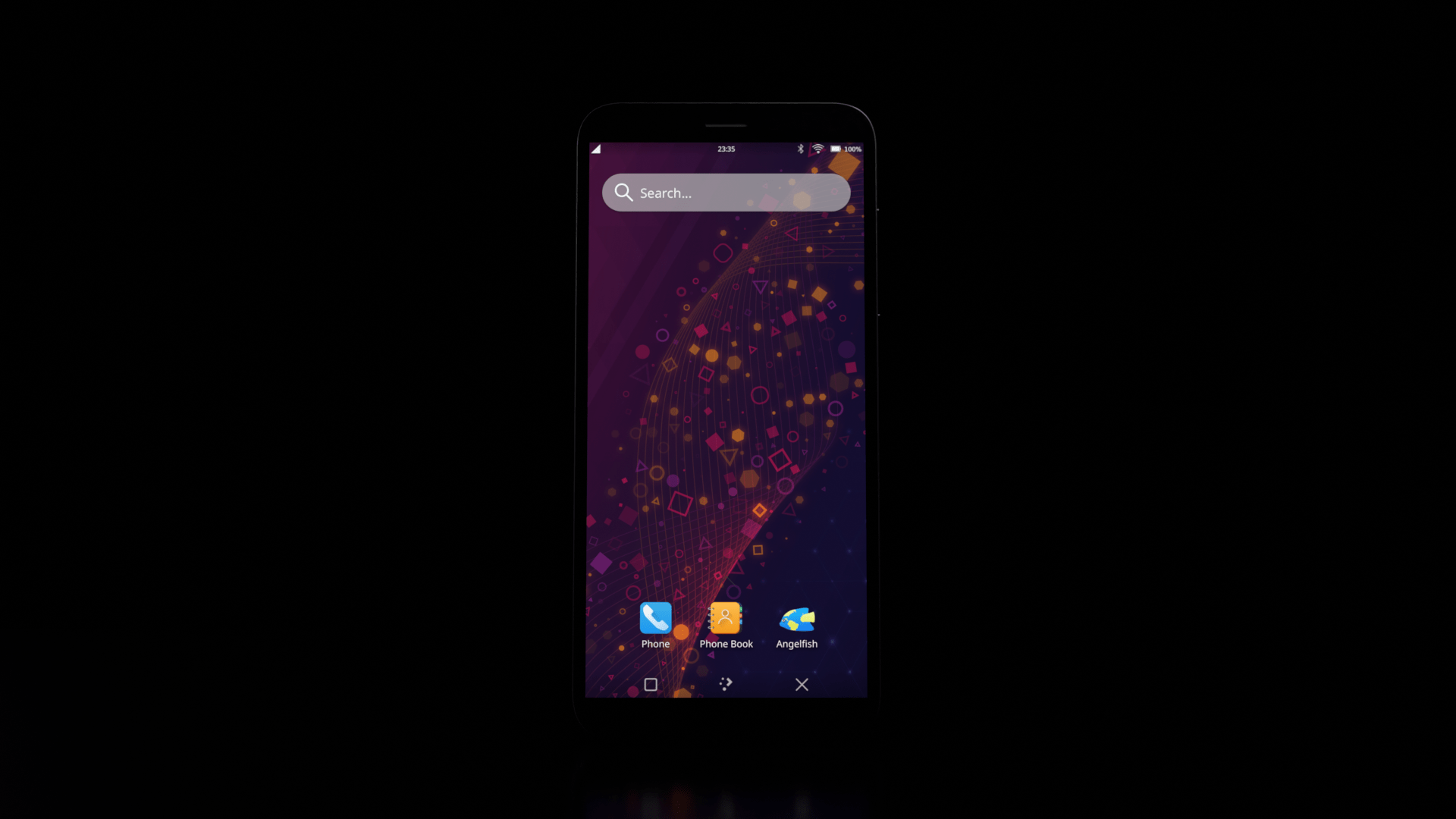
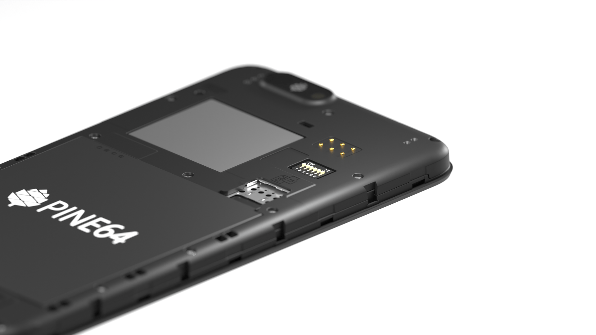
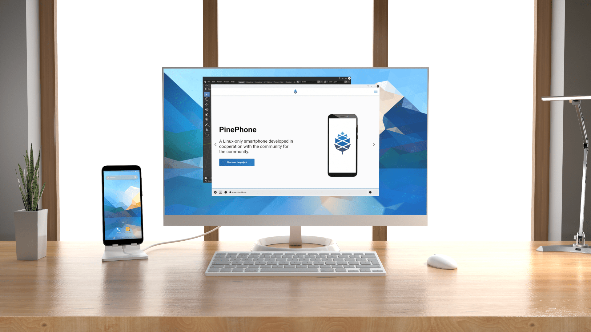

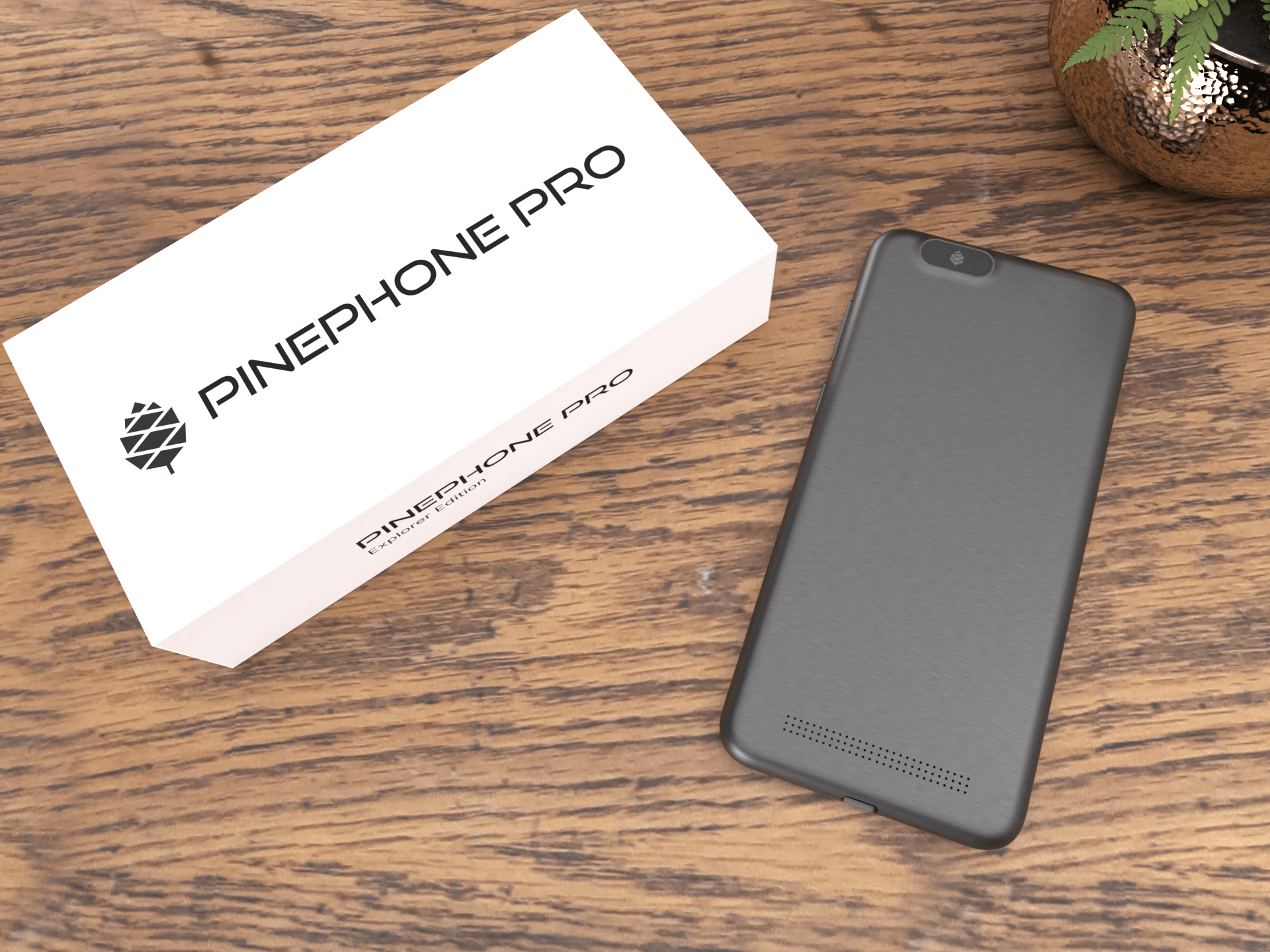

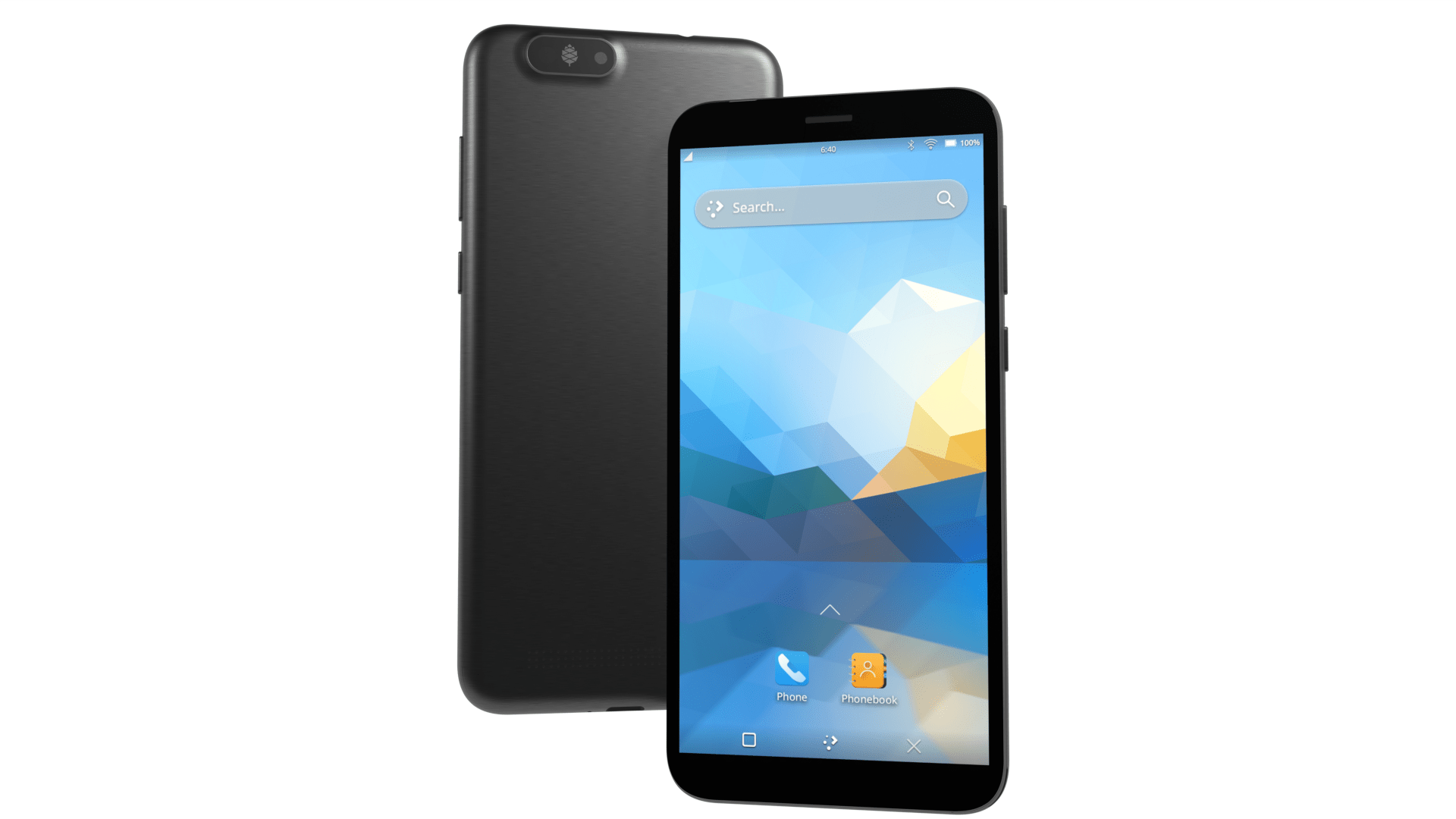
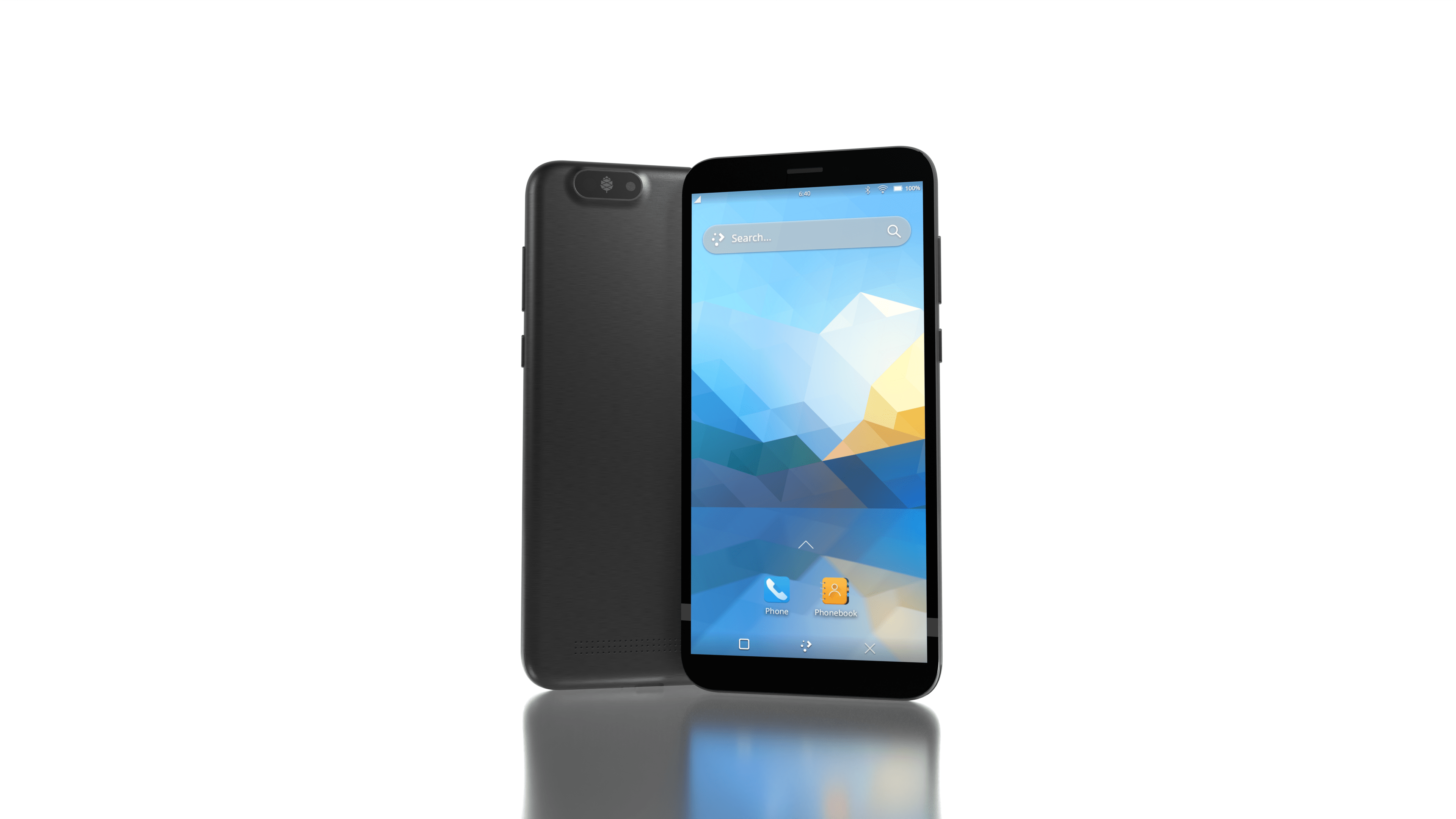
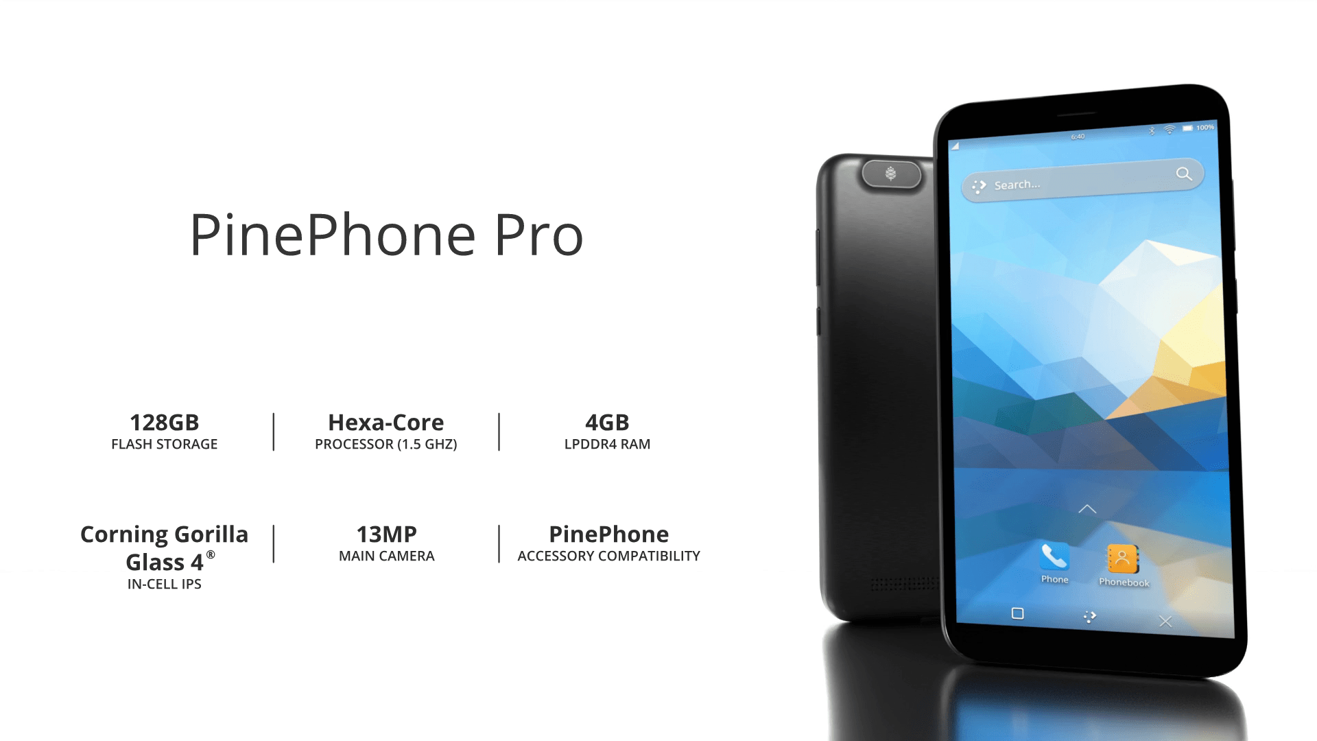
PinePhone
Beta Edition. Author: Funeral, License: CC0 Author: Funeral, License: CC0

3D model
The 3D model can be used for a wide variety of purposes, for example for product renderings:
Example rendering:
Author: Funeral, License: CC0 Author: Funeral, License: CC0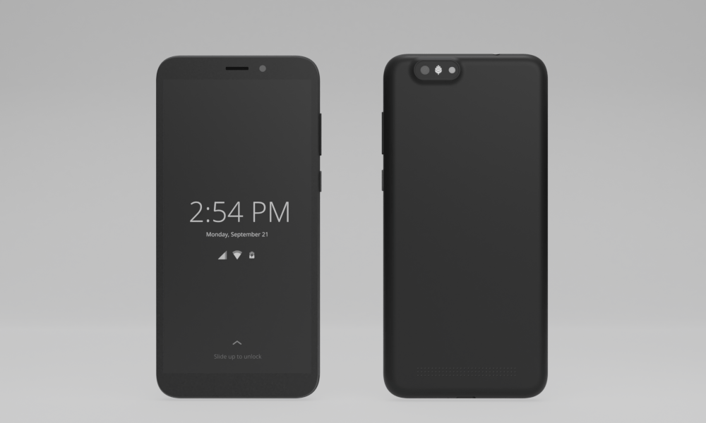
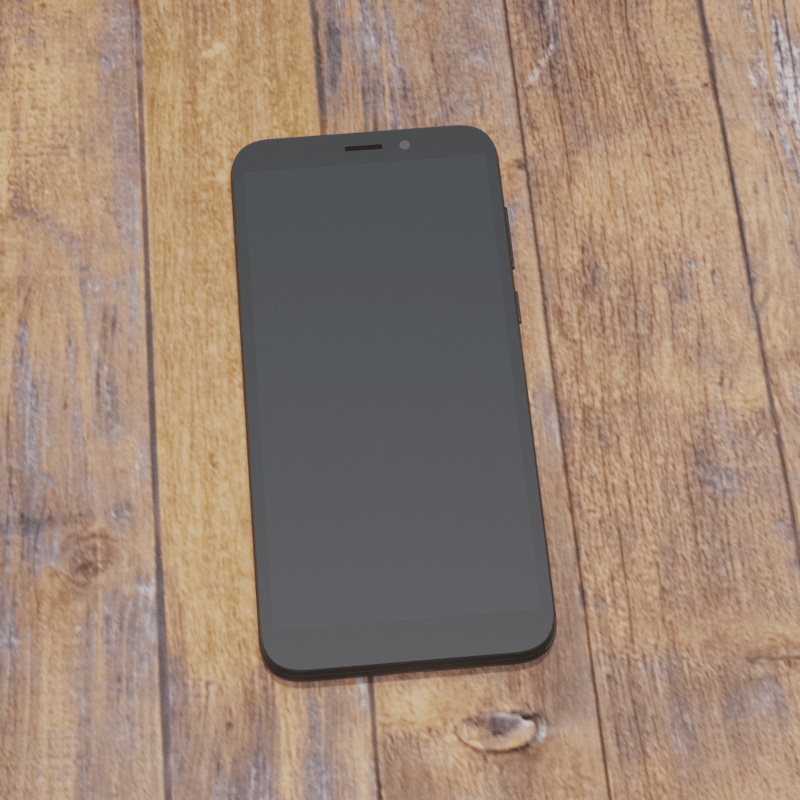
New template:
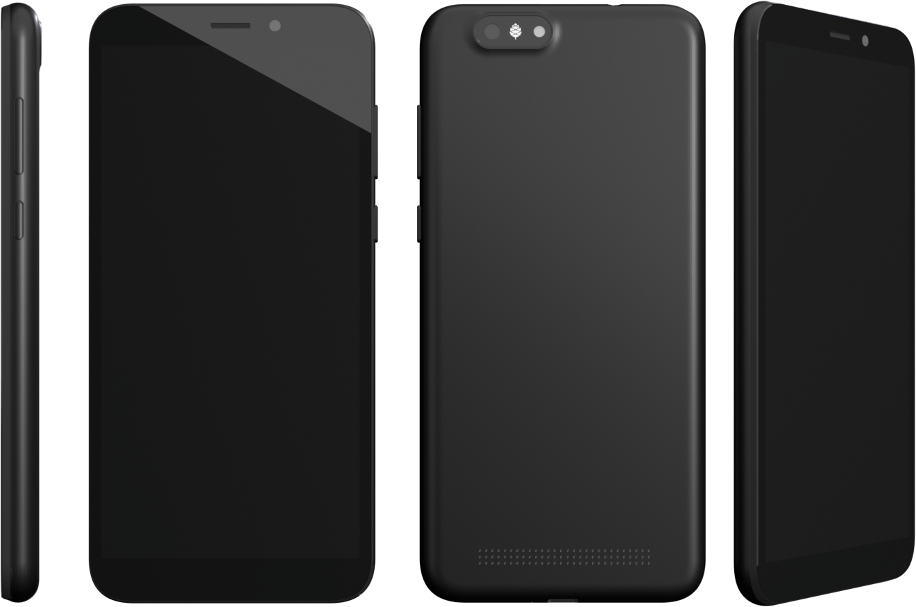
Author: Funeral, License: CC0
Old template:
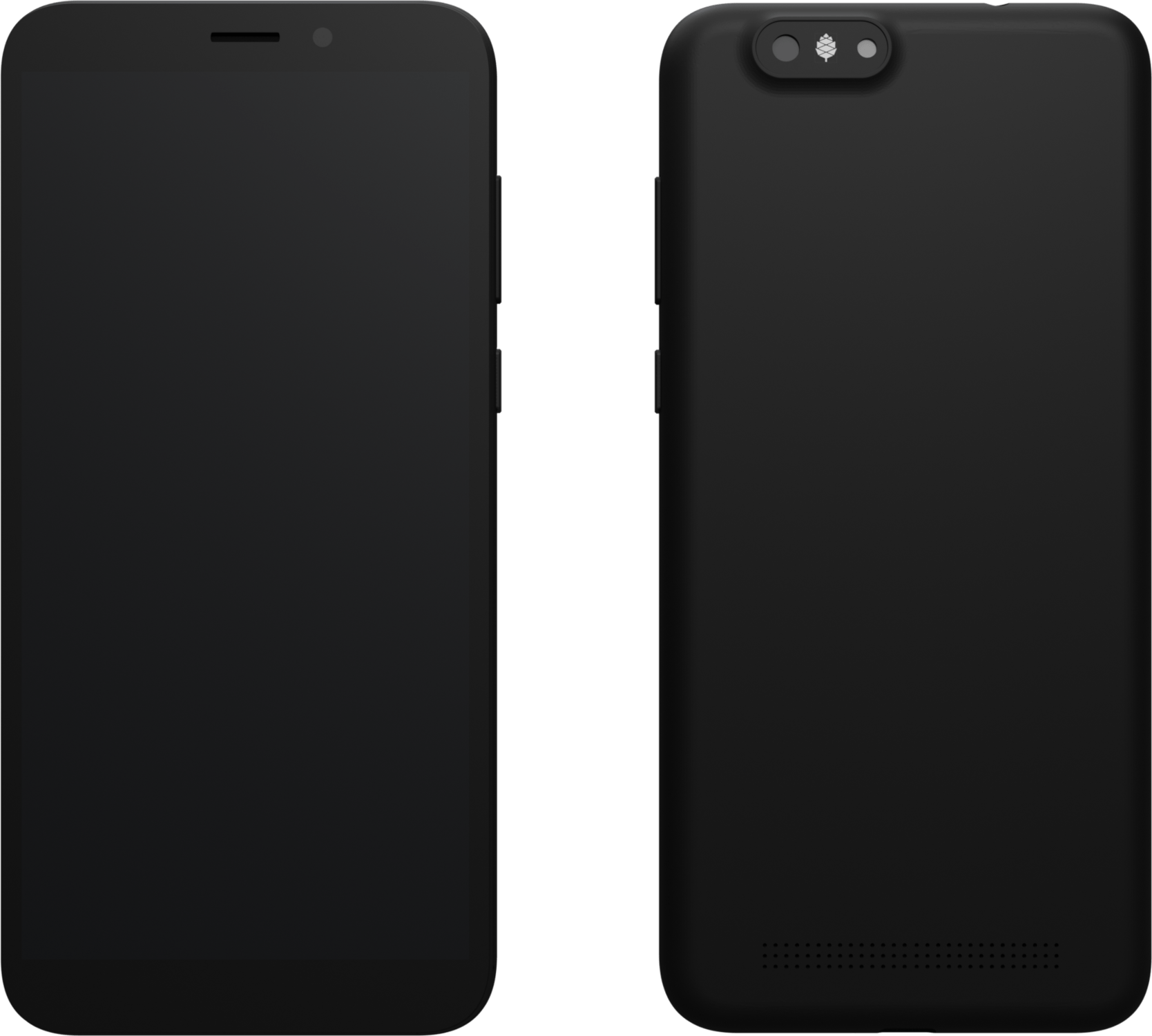
Author: Funeral, License: CC0
Lockscreen template
For renderings you can use and modify this template:
Version with black background. Author: Funeral, License: CC0. Version with no background. Author: Funeral, License: CC0.

Manual and Instructions

Author: Jedi2light, License: CC BY 4.0

Author: Funeral, License: CC0

Author: Funeral, License: CC0
Author: Funeral, License: CC0 Author: Funeral, License: CC0 Author: Funeral, License: CC0
Author: Funeral, License: CC0 Author: Funeral, License: CC0 Author: Funeral, License: CC0

Author: Funeral, License: CC0

Author: Funeral, License: CC0

Author: Funeral, License: CC0

Author: Funeral, License: CC0
Resources
The following resources have been made available by Ondřej Jirman, a developer for the Pinephone:
- Getting started with PinePhone Hardware
- State of development progress
- Development log
- PinePhone Technical News and Update, also applies to other Allwinner devices including PINE A64 SBC
- Contributions to the kernel development
Safety
General recommendations
Due to the greater control the user is having over the device and its software comes also greater responsibility. It is necessary to verify the configuration of the device to make sure that responsible settings are used. The different operating systems may come with non-sane default settings, including SSH with weak password authentication being enabled by default and exposed to the public Internet, the absence of a firewall, default passwords, unencrypted files, too high temperature zones and emergency shutoff values or an enabled root account. The usage of public resources to verify such settings (such as the in case of GNU/Linux, the Arch Linux security wiki page, or the general recommendations) as well as the corresponding operating system’s or distribution’s resources are strongly recommended.
Charging safety
The PinePhone supports up to 5V 3A (15W) Quick Charge, it follows the USB Power Delivery specification. Only compatible phone chargers may be used, charging the phone with incompatible chargers (for example laptop chargers with a higher voltage) is prohibited. Charging the phone releases heat, general safety recommendations must be followed, see the section Thermal safety.
Thermal safety
With the Allwinner A64 being an older generation SoC with a large 40nm chip, the phone produces quite some heat with medium or higher use and especially also during charging or when using USB accessories, like a docking station. Measurements to prevent damage to the phone and to its surroundings need to be taken by the user. This includes especially a proper handling of the phone: do not charge the phone in a way where heat builds up around the phone without being able to escape. Especially don’t charge your phone under a pillow, blankets, in pockets or bags. Charging the phone produces heat and charging the phone in a way, where the excessive heat can’t dispose around the phone poses an immediate fire risk.
The user might notice that the phone gets warm under usage, compared to phones with more up-to-date hardware. Under normal circumstances these temperatures don’t pose a risk while being in the levels within the safe operating temperatures (which lay far beyond the point where components can be too hot to touch). Higher temperatures might especially be experienced on the top side of the screen and on the inside of the phone at the RF shield of the modem. The higher temperature of the RF shield of the modem is commonly caused by the SoC on the opposite side of the mainboard, the RF shield of the modem is used to disperse heat of the SoC. In newer mainboard revisions starting from 1.2a there are also thermal pads on the back cover and between the SoC’s RF shield and the screen, dispersing heat on the screen and on the back cover. In the past there has been safety issues regarding thermal safety functions, causing temperature reads to not properly work over an extended period of time, which was causing heat damage in some cases (see the documentation of that issue by the developer Megous here and here). While the developers are working hard to prevent such issues, they can’t be excluded under all circumstances. The users are expected to monitor their phones’ thermal safety at every point at this state of the software.
It is highly recommend to update the phone on a regular basis to always get the latest improvements. The default settings to throttle the performance and to shut down the phone when reaching critical temperatures might be set to a too high point depending on the specific usage and usage length. Under GNU/Linux the phone’s thermal management behavior can be modified via the Thermal Sysfs driver to achieve lower temperatures and preventing the screen and other components to potentially take damage, see Thermal tweaks for the details.
Schematics and certifications
PinePhone mainboard schematic:
- PinePhone mainboard Released Schematic ver 1.2b
- PinePhone mainboard Released Schematic ver 1.2a
- PinePhone mainboard Released Schematic ver 1.2
- PinePhone schematic ver 1.2 change list
- “Braveheart” PinePhone mainboard Schematic ver 1.1
- “Braveheart” PinePhone mainboard component top placement drawing ver 1.1
- “Braveheart” PinePhone mainboard component bottom placement drawing ver 1.1
- Components list
PinePhone USB-C small board schematic:
- PinePhone USB-C small board Schematic ver 1.0
- PinePhone USB-C small board component top placement drawing ver 1.0
- PinePhone USB-C small board component bottom placement drawing ver 1.0
PinePhone certifications:
- PinePhone FCC Certificate
- RF Exposure SAR Information from FCC ID site
- PinePhone CE RED Certificate
- PinePhone ROHS Report
- Note: PinePhone’s Type Allocation Code (TAC) is 86769804
Sensors and navigation
Please help to review and edit this page or section. Information are subject to change.
Overview
The PinePhone contains various components that enable or aid orientation and navigation tasks.
- Multi-GNSS Receiver as part of the cellular modem (GPS/Galileo/GLONASS/BeiDou)
- IMU (Inertial Measurement Unit), combined Accelerometer and Gyroscope sensor (MPU6050)
- Magnetometer (LIS3MDL or AF8133J)
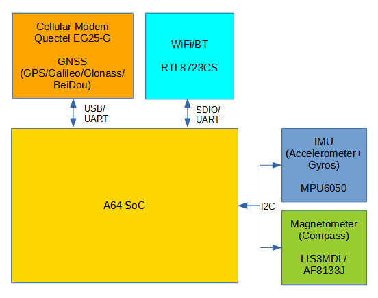
PinePhone navigation sensors
Hardware
Quectel EG25G Modem / GNSS Receiver
Invensense/TDK MPU6050 IMU
Key features:
- Digital-output X-, Y-, and Z-Axis angular rate sensors (gyroscopes) with selectable range of ±250, ±500, ±1000, and ±2000°/sec
- Digital-output triple-axis accelerometer with a programmable full scale range of ±2g, ±4g, ±8g and ±16g
- 400 kHz Fast Mode I2C for communicating with all registers
ST LIS3MDL Magnetometer/Compass
Key features:
- ±4/±8/±12/±16 gauss selectable magnetic full scale range
- 16-bit data output
- …
VTC AF8133J Magnetometer/Compass
Key features:
- ±12/±22 gauss selectable magnetic full scale range
- 400Hz max. update rate
- 16-bit data output
Sensor reference frames
The sensors are mounted on the PinePhone’s mainboard in different positions and orientations. For the purpose of orientation and navigation it is important to know the relationship between the sensor coordinate frames and the body frame of the phone.
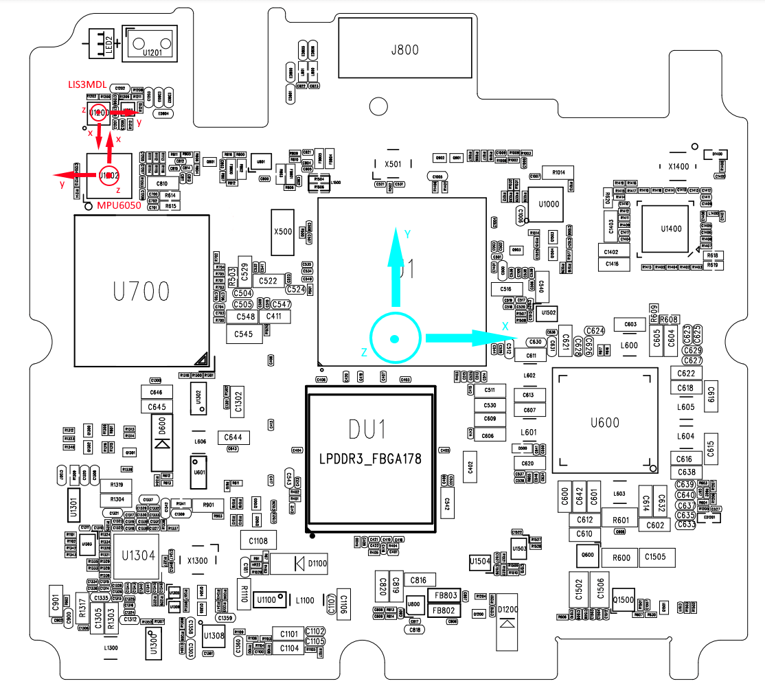
PinePhone sensor coordinates systems (red) and body coordinate system (cyan)
As a basis for software development, a common body coordinate system has to be established along with it’s relation to a world coordinate system. “iio-sensor-proxy expects the (sensor) readings to match those defined in the Linux IIO documentation, the Windows Integrating Motion and Orientation Sensors whitepaper, and the Android sensor documentation”[ref]. To transform the sensor coordinate systems into body coordinates, ‘mount matrices’ have to be defined.
TODO: explain body reference choices, north-east-down world coordinates
Software
Drivers
TODO: i2cdev, linux-iio, support matrix
- EG25G: provides either UART or USB based interfaces for NMEA data
- /dev/ttyUSB2: AT command interface
- /dev/ttyUSB1: default NMEA data output
- MPU6050:inv_mpu6050, inv_mpu6050_i2c, industrialio
iio:device2: mpu6050 (buffer capable)
	9 channels found:
		accel_x:  (input, index: 0, format: be:S16/16>>0)
		6 channel-specific attributes found:
			attr  0: calibbias value: -2102
			attr  1: matrix value: 0, 0, 0; 0, 0, 0; 0, 0, 0
			attr  2: mount_matrix value: 0, 1, 0; -1, 0, 0; 0, 0, -1
			attr  3: raw value: 912
			attr  4: scale value: 0.000598
			attr  5: scale_available value: 0.000598 0.001196 0.002392 0.004785
		accel_y:  (input, index: 1, format: be:S16/16>>0)
		6 channel-specific attributes found:
			attr  0: calibbias value: 941
			attr  1: matrix value: 0, 0, 0; 0, 0, 0; 0, 0, 0
			attr  2: mount_matrix value: 0, 1, 0; -1, 0, 0; 0, 0, -1
			attr  3: raw value: 516
			attr  4: scale value: 0.000598
			attr  5: scale_available value: 0.000598 0.001196 0.002392 0.004785
		accel_z:  (input, index: 2, format: be:S16/16>>0)
		6 channel-specific attributes found:
			attr  0: calibbias value: 1242
			attr  1: matrix value: 0, 0, 0; 0, 0, 0; 0, 0, 0
			attr  2: mount_matrix value: 0, 1, 0; -1, 0, 0; 0, 0, -1
			attr  3: raw value: 15860
			attr  4: scale value: 0.000598
			attr  5: scale_available value: 0.000598 0.001196 0.002392 0.004785
		temp:  (input)
		3 channel-specific attributes found:
			attr  0: offset value: 12420
			attr  1: raw value: -1073
			attr  2: scale value: 2.941176
		anglvel_x:  (input, index: 4, format: be:S16/16>>0)
		5 channel-specific attributes found:
			attr  0: calibbias value: 0
			attr  1: mount_matrix value: 0, 1, 0; -1, 0, 0; 0, 0, -1
			attr  2: raw value: -32
			attr  3: scale value: 0.001064724
			attr  4: scale_available value: 0.000133090 0.000266181 0.000532362 0.001064724
		anglvel_y:  (input, index: 5, format: be:S16/16>>0)
		5 channel-specific attributes found:
			attr  0: calibbias value: 0
			attr  1: mount_matrix value: 0, 1, 0; -1, 0, 0; 0, 0, -1
			attr  2: raw value: 4
			attr  3: scale value: 0.001064724
			attr  4: scale_available value: 0.000133090 0.000266181 0.000532362 0.001064724
		anglvel_z:  (input, index: 6, format: be:S16/16>>0)
		5 channel-specific attributes found:
			attr  0: calibbias value: 0
			attr  1: mount_matrix value: 0, 1, 0; -1, 0, 0; 0, 0, -1
			attr  2: raw value: 0
			attr  3: scale value: 0.001064724
			attr  4: scale_available value: 0.000133090 0.000266181 0.000532362 0.001064724
		timestamp:  (input, index: 7, format: le:S64/64>>0)
		gyro:  (input, WARN:iio_channel_get_type()=UNKNOWN)
		1 channel-specific attributes found:
			attr  0: matrix value: 0, 0, 0; 0, 0, 0; 0, 0, 0
	3 device-specific attributes found:
			attr  0: current_timestamp_clock value: realtime
			attr  1: sampling_frequency value: 50
			attr  2: sampling_frequency_available value: 10 20 50 100 200 500
	2 buffer-specific attributes found:
			attr  0: data_available value: 0
			attr  1: watermark value: 1
	Current trigger: trigger1(mpu6050-dev2)
- LIS3MDL: st_sensors, st_sensors_i2c, st_magn, st_magn_i2c, industrialio
iio:device1: lis3mdl (buffer capable)
	4 channels found:
		magn_x:  (input, index: 0, format: le:S16/16>>0)
		3 channel-specific attributes found:
			attr  0: raw value: 6766
			attr  1: scale value: 0.000146
			attr  2: scale_available value: 0.000146 0.000292 0.000438 0.000584
		magn_y:  (input, index: 1, format: le:S16/16>>0)
		3 channel-specific attributes found:
			attr  0: raw value: -2046
			attr  1: scale value: 0.000146
			attr  2: scale_available value: 0.000146 0.000292 0.000438 0.000584
		magn_z:  (input, index: 2, format: le:S16/16>>0)
		3 channel-specific attributes found:
			attr  0: raw value: 12726
			attr  1: scale value: 0.000146
			attr  2: scale_available value: 0.000146 0.000292 0.000438 0.000584
		timestamp:  (input, index: 3, format: le:S64/64>>0)
	3 device-specific attributes found:
			attr  0: current_timestamp_clock value: realtime
			attr  1: sampling_frequency value: 1
			attr  2: sampling_frequency_available value: 1 2 3 5 10 20 40 80
	2 buffer-specific attributes found:
			attr  0: data_available value: 0
			attr  1: watermark value: 1
	Current trigger: trigger0(lis3mdl-trigger)
Userspace services
TODO: …
- Modem Manager
- ofono
- gpsd
- iio-sensor-proxy
- geoclue
Tools/Utilities
TODO: minicom, gpsmon, monitor-sensor, iio-utils…
Applications
TODO: pure-maps, navit, …
Development
TODO: Open issues, tasks, projects
Open issues
- AGPS integration
- how to enable/disable the service?
- update triggers?
- network connectivity?
- agps data valid?
- Raw magnetometer handling
- Issue: Support polling/non-compensated magnetometers in iio-sensor-proxy
- Issue: raw magnetometer calibration implementation
- GPS/Compass App
- TODO: specification
Frameworks/APIs/…
- Modem Manager location API
- oFono location API (experimental?)
- geoclue API
Specifications
- Dimensions: 160.5 x 76.6 x 9.2mm
- Weight: Between 180 ~ 200 grams
- SIM Card: Micro-SIM
- Display:
- Size: 5.95 inches (151mm) diagonal
- Type: HD IPS capacitive touchscreen, 16M colors
- Resolution: 1440x720, 18:9 ratio
- System on Chip: Allwinner A64
- RAM: 2GB or 3GB LPDDR3 SDRAM
- Internal Storage: 16GB or 32GB eMMC, extendable up to 2TB via microSD, supports SDHC and SDXC
- Back Camera: Single 5MP, 1/4", LED Flash
- Front Camera: Single 2MP, f/2.8, 1/5"
- Sound: Loudspeaker, 3.5mm jack & mic (jack doubles as hardware UART if hardware switch 6 is deactivated)
- Communication:
- Modem: Quectel EG25-G
- LTE-FDD: B1, B2, B3, B4, B5, B7, B8, B12, B13, B18, B19, B20, B25, B26, B28
- LTE-TDD: B38, B39, B40, B41
- WCDMA: B1, B2, B4, B5, B6, B8, B19
- GSM: B2, B3, B5, B8 (850, 900, 1800, 1900 MHz)
- WLAN: Wi-Fi 802.11 b/g/n, single-band, hotspot
- Bluetooth: 4.0, A2DP
- GNSS: GPS/GLONASS/BeiDou/Galileo/QZSS, with A-GPS
- Sensors: Accelerometer, gyroscope, proximity, ambient light, compass
- Privacy switches: Modem, WiFi & Bluetooth, Microphone, Cameras
- Battery: Lithium-ion, rated capacity 2800mAh (10.64Wh), typical capacity 3000mAh (11.40Wh) (nominally replaceable with any Samsung J7 form-factor battery)
- I/O: USB Type-C, USB Host, DisplayPort Alternate Mode output, 15W 5V 3A Quick Charge, follows USB PD specification


