Disassembly and Reassembly
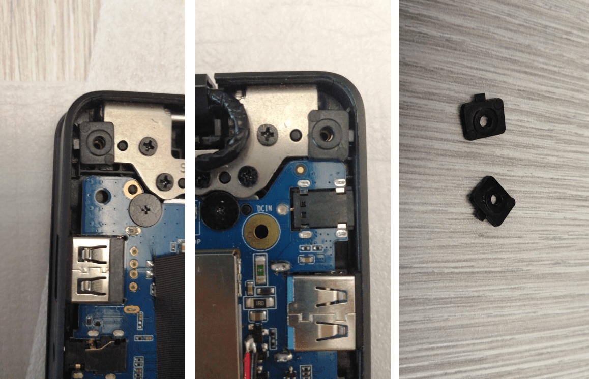
Pinebook Screw stand-offs correct placement and location
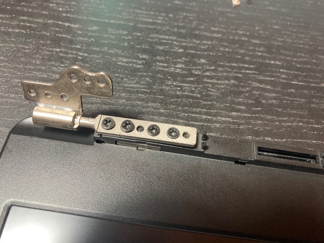
Hinge_area_of_the_Pinebook_Pro_lid_with the cover removed Close-up of a Pinebook Pro lid hinge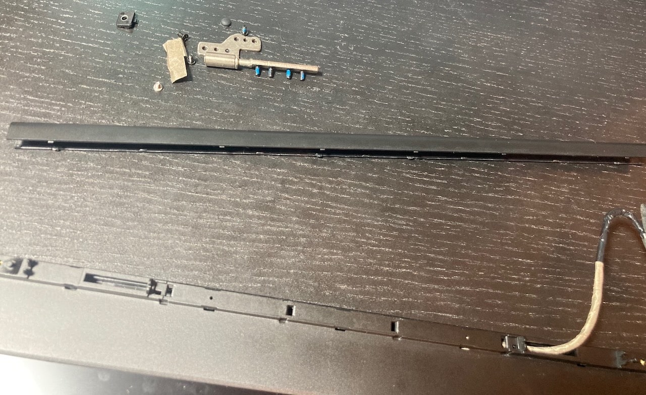
There are a few mandatory precautions to be taken:
- Do not open the laptop by lifting the lid while the Pinebook Pro bottom cover is removed - this can cause structural damage to the hinges and/or other plastic components of the chassis such as the IO port cut-outs.
- When removing the back cover plate, do not, under any circumstances, slide your fingertips between the metal shell and the plastic frame! The back cover plate edges are sharp, and when combined with the pressure and movement generated from, specifically, attempting to slide the tips of your fingers along the bottom edge of the plate along the lid-hinge, they will slice open the tips of your fingers like a knife.
- When removing the back cover plate, use care to avoid damaging the speakers. They can be stuck to the back cover with double-sided tape, and the thin wires are very delicate. Newer Pinebook Pro laptops (as of the May 2021 batch, and perhaps earlier) seem to lack the double-sided tape to the rear cover, instead opting for tape or glue that makes them stick to the front cover. Nevertheless, be gentle when removing the back cover.
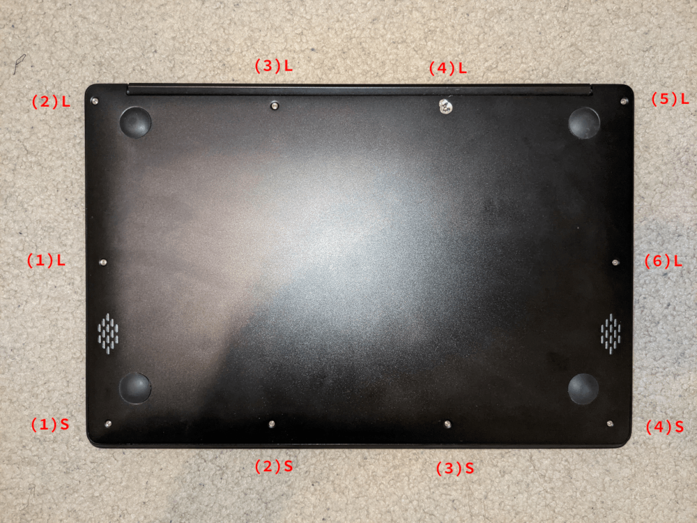
Pinebook Pro external screws (this particular unit has suffered damage on screw (4)L)
When disassembling the laptop make sure that it is powered off and folded closed. To remove the bottom cover of the Pinebook Pro, first remove the ten (10) Phillips head screws that hold the bottom section of the laptop in place. There are four (4) short screws along the front edge, and six (6) long screws along the 3 remaining sides. Remove the cover from the back where the hinges are situated by lifting it up and away from the rest of the chassis. The aluminum case is held on only by screws. There are no plastic snaps, and the shell should pull away without any effort. If you experience any resistance at all stop and ensure all ten (10) screws are accounted for.
During reassembly, make sure that the back-screw standoffs are in place and seated correctly. Before replacing the aluminum back-plate, ensure that the speakers are properly seated by pressing gently on the hard plastic edge of the speaker module. Slide the bottom section into place so it meets the front lip of the keyboard section. Secure the front section (where the touchpad is located) in place using the short screws in the front left and right corners. Then proceed to pop in the bottom panel into place. Secure the bottom section (where hinges are located) by screwing in the left and right corners. Then screw in the remaining screws and run your finger though the rim on the chassis to make sure its fitted correctly. Note that the front uses the remaining 4 short screws.
The screws are small and should only be finger tight. Too much force will strip the threads. If after installing screws the back cover plate has not seated properly on one side (which may be caused by the aforementioned misseating of the speakers), open the display and hold the base on either side of the keyboard and gently flex the base with both hands in opposing directions. Once the side pops further in, then recheck the screws on that side. If it does not pop back in, re-open the machine and check for misseated components.
A basic 3D model to print replacement standoffs for the back cover screws is available on Thingiverse, until the official drawings or 3D models are made available.
Many units come with the hinges too stiff from the factory. You can tell if it affects your device by carefully observing if operating the lid on a fully assembled notebook flexes the case. This repeated flexing can lead to plastic and metal fatigue and eventually broken parts. Consider carefully using a flat screwdriver or similar object to unbend the hinges a bit by wedging it into the slot (requires the display part to be fully detached from the main body).
Display disassembly
It is not recommended to adjust the position of the lid when the bottom cover is removed, because the bottom cover provides structural strength, so the lid should be open fully as the first step, before starting any disassembly of the laptop. After opening the lid, remove the bottom cover by following the instruction found in the section above. Alternatively, you can keep the lid closed and remove the screws that hold the hinges to the main laptop body, as described in Pinebook Service Step by Step Guides.
Parts of the hinge mechanism, as well as the screws that hold the hinges to the lid, are hidden behind an elongated plastic U-shaped cover that snaps in place using latches. Use a dedicated plastic prying tool or a guitar pick to gently pry the cover and remove it, starting from the outer edge. Once you pry the cover to a certain extent, it should be possible to remove it fully using only your hands. The U-shaped cover is rather sturdy, but still be careful not to break or bend it.
There are two small screws hidden underneath the two small rubber nubs on the upper part of the screen bezel, so first gently remove the nubs and then remove the screws. The screen bezel is held in place with a combination of latches and some adhesive tape, which is there to prevent dust ingress. The adhesive isn’t very strong, and the bezel is capable of flexing back into shape after being twisted to a certain extent. There is more adhesive on the bottom part of the screen bezel, so be more careful while prying that section apart. Use the same prying tool that you used for the U-shaped cover, and work it around the outer edges of the screen bezel.