Pinebook Pro (Single Page)
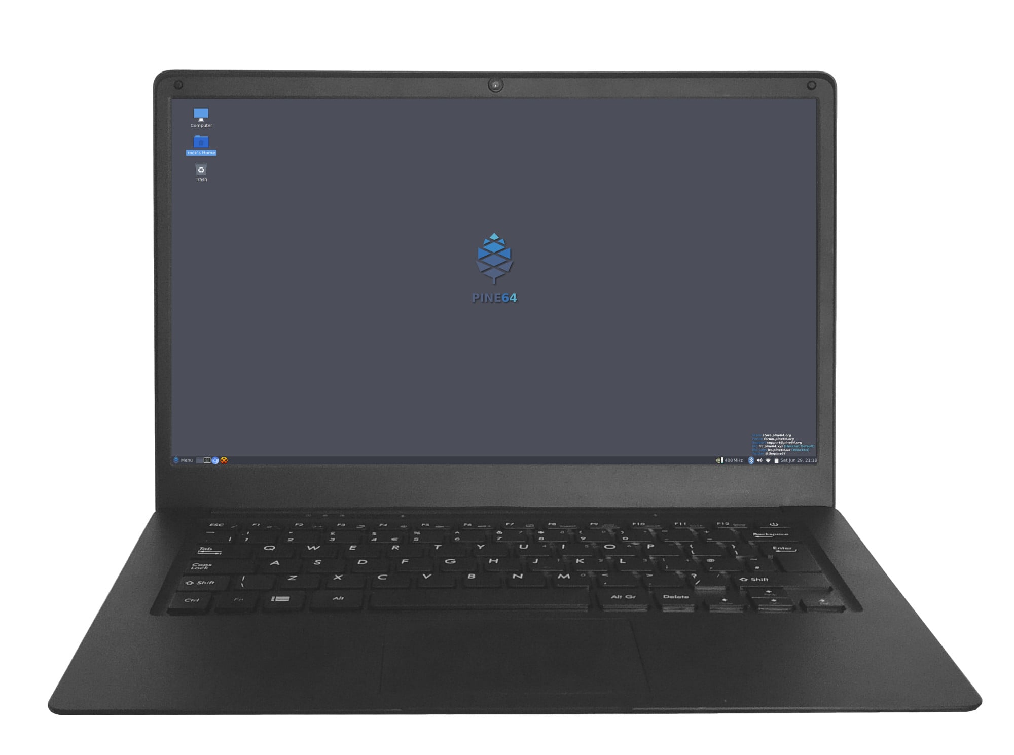
Pinebook Pro running Debian with MATE
The Pinebook Pro is a Linux and *BSD ARM laptop from PINE64. It is built to be a compelling alternative to mid-ranged Chromebooks that people convert into Linux laptops.
The Pinebook Pro features an IPS 1080p 14″ LCD panel, a premium magnesium alloy shell, high capacity eMMC storage, a 10,000 mAh (9,600 mAh in later batches) capacity battery, and the modularity that only an open source project can deliver with the dimensions of 329mm x 220mm x 12mm (WxDxH). Key features include the Rockchip RK3399 SoC, USB-C for data, video-out and power-in (2.5 A at 5 V), privacy switches for the microphone, BT/WiFi module, camera and expandable storage via NVMe (PCIe x4) with an optional adapter.
The Pinebook Pro is equipped with 4 GB of LPDDR4 system memory, up to 128 GB of eMMC flash storage, and 128 Mbit of SPI boot flash. The I/O includes: 1 x micro SD card reader (bootable), 1 x USB 2.0, 1 x USB 3.0, 1 x USB Type-C host with DP 1.2 and power-in, PCI Express x4 for an M.2 NVMe SSD drive (requires an optional adapter), and serial console UART (via the headphone jack by setting an internal switch). The keyboard and touchpad both use the USB 2.0 protocol. The LCD panel uses the eDP MiPi display protocol.
Versions
Pinebook Pro v1 and v2 were prototype models that did not make it to the public. The “first batch” (first 100 forum pre-orders) onward are v2.1. [https://forum.pine64.org/showthread.php?tid=8111]
Software
Releases
This page contains a list of all available releases and tools for the Pinebook Pro.
Linux OS Image Releases
For information on how to install these images onto your device, please see the Getting started Page, which includes information on writing images to the device eMMC or an SD card
Manjaro ARM

The Manjaro project offers a mainline kernel with patches and modules to support the Pinebook Pro hardware. To learn more about Manjaro please visit Manjaro Forum. You can follow the ongoing discussion about Manjaro on the PINE64 forum. All images boot from both SD card and the internal eMMC module.
Download:
- Direct download from Manjaro: You have to navigate to the Manjaro ARM section and select “Generic” as the device in the drop-down list (the Pinebook Pro image has been removed and it’s now included in the generic one since version 22.08). Then you can choose Gnome, KDE Plasma, Mate, Minimal, Sway or Xfce.
- Old factory release: Manjaro/Plasma 22.06 factory loaded build (June 2022) from pine64.org (1.04GB, MD5 of the XZ file d78031a4bed3eeb4f2001f3c89b9ed5a)
Armbian

Armbian is a base operating system platform for single board computers (SBCs) that other projects can trust to build upon. It is a lightweight Debian or Ubuntu based Linux distribution specialized for ARM development boards. Each system is compiled, assembled and optimized by the Armbian Build Tools. It has powerful build and software development tools to make custom builds and a vibrant community.
Download:
Notes:
- If you have any difficulties please visit our forum or come chat with us on IRC / Discord
- As of April 2023, Armbian only has Ubuntu images pre-made. However, using their tools to create a Debian image from scratch takes little expertise and results in an image that can be burned onto a USB stick or SD card. Their installer can then install it onto internal eMMC, including a working bootloader.
Twister OS

Twister OS Armbian-Reforged with Xfce. It boots from microSD card and from eMMC. For more information on Twister OS, please visit this official site. You can follow the ongoing discussion about Twister OS on the PINE64 forum.
Installation
- After flashing image, edit /boot/armbianEnv.txt, replace the dtb name with
rk3399-pinebook-pro.dtb
Download location
Get the latest image here: Direct download latest images from Twister OS’s website (size: 2.8GB)
Password
| Default credentials | |
|---|---|
root | asdasd |
Fedora

Fedora Linux is a Linux distribution developed by the Fedora Project. It creates an innovative, free, and open source platform for hardware, clouds, and containers that enables software developers and community members to build tailored solutions for their users.
Installation:
- Using this blog post it is possible to run Official Fedora on the Pinebook Pro
Notes:
- Upstream Fedora uses the SPI flash on the Pinebook Pro to manage U-Boot.
Arch Linux ARM

Official Installation
See Installing Arch Linux ARM for instructions on how to install the official Arch Linux ARM.
Customized Premade Root Filesystem
An Arch Linux ARM root filesystem customized for the Pinebook Pro using Manjaro’s kernel is available. Instructions are included for installation on microSD card, eMMC module and NVMe SSD.
Download location
Get the latest root filesystem from GitHub (size: 500-600 MB).
Installation
Make sure to thoroughly read the readme, installation instructions and FAQ.
Username and password
The default Arch Linux ARM user credentials.
| Default credentials | |
|---|---|
alarm | alarm |
root | root |
postmarketOS

Official postmarketOS stable builds are available for the Pinebook Pro with the following interfaces:
- console
- GNOME
- KDE Plasma Desktop
- Phosh
- Sway
It boots from microSD card and from eMMC.
Download location
Get the stable image here: https://postmarketos.org/download/ (size: 103 MB to 775 MB)
The installer images allows setting up an encrypted installation on SD or eMMC.
Username and password
| Default credentials | |
|---|---|
user | 147147 |
Kali Linux

Official pre-built OS images of Kali Linux for the Pinebook Pro featuring all tools you’d expect from the distribution. It boots from microSD card and from eMMC.
Download location
Get the latest image here: Direct download latest images from Offensive Security’s website (size: 2.0 GB)
Username and password
| Default credentials | |
|---|---|
kali | kali |
R-Cade

Retro Center’s R-Cade [USB / microSD / eMMC Boot]
- The 4K Media Center Arcade
- RCade Features 100+ retro-gaming systems, a lightweight web browser, and full 4K UHD media playback
- DD image to USB, microSD, or eMMC and boot. Highly recommend using Etcher
Username and password
| Default credentials | |
|---|---|
root | retro |
Q4OS

Q4OS is advertised as a ‘fast and powerful operating system based on the latest technologies while offering highly productive desktop environment’. It boots from microSD card and from eMMC. To learn more please visit the PINE64 forum or official Q4OS website.
Download location
Get the latest image here: Direct download latest release build from SourceForge
Username and password
User account and password are created on first run.
DietPi

DietPi is a lightweight, yet easy to setup and feature-rich Linux distribution, based on Debian. To find out more about DietPi, please visit the official documentation. Discuss the Pinebook Pro build on the PINE64 forum thread.
Download:
| Default credentials | |
|---|---|
root | dietpi |
openSUSE

Download location
Get the latest openSUSE Tumbleweed images for Pinebook Pro here: https://en.opensuse.org/HCL:Pinebook-Pro-RK3399. Credits to https://bugzilla.opensuse.org/show_bug.cgi?id=1194491.
- Step 1. Flash Tow-Boot to SPI
- Step 2. Flash openSUSE image to sd card & insert it
- Step 3. When it loads grub, press e and add the following line:
devicetree /boot/dtb/rockchip/rk3399-pinebook-pro.dtb
Press ctrl + x to boot
Works: display, WiFi Not tested: bluetooth Doesn’t work: audio
You may build RPMs and see if it fix issues from this repository: https://github.com/bengtfredh/pinebook-pro-copr
Default password for root is “linux”
FydeOS
An operating system based on the Chromium Project
https://fydeos.io/download/device/pinebook-pro
Void Linux

Images
Void Linux packages U-Boot and a kernel for the Pinebook Pro, but does not distribute any images for the device.
Cameron Nemo (User:CameronNemo) distributes unofficial Void Linux images for the Pinebook Pro:
Some notes about the images:
- They were released on 2022-05-30 (glibc) and 2022-06-10 (musl)
- They ship U-Boot 2022.04 and Linux 5.15 (with minimal patches)
- Meant to be uncompressed then flashed to either an SD card or the internal eMMC module
- The root partition is ~1.7GB, and must be expanded manually
- There are very few services enabled on the images by default: udev and some getty’s
| Default credentials | |
|---|---|
root | voidlinux |
Do It Yourself
You can also manually install Void from a rootfs tarball: see instructions here.
BSD
NetBSD

The image boots from microSD card and from eMMC. To learn more about NetBSD please visit NetBSD main page
Download location
Get the latest image here: Direct download from NetBSD
Installation
Instructions concerning enabling SSH can be found here.
Username and password
| Default credentials | |
|---|---|
root | none |
OpenBSD

The image boots from microSD card and from eMMC. To learn more about OpenBSD, please visit OpenBSD main page
Download location
ARM64 images, (including support for Pinebook Pro), can be found here OpenBSD arm64
Linux Installer Releases
Manjaro ARM

The manjaro-arm-installer script is intended to install Manjaro ARM directly to SD/eMMC cards without the need for images (including LXQT, Mate & CuboCore editions, as well as full disk encryption).
Running on a Linux x86 computer, it can install Manjaro ARM directly to an empty eMMC using an eMMC to USB adapter. The script can also be run from SD to install an image to the eMMC.
Armbian

You can use the Armbian Builder to generate your own Armbian images of various types.
The builder supports building any version of Debian and any version of Ubuntu with various desktop options:
- Budgie
- Cinnamon
- Deepin
- Enlightenment
- Gnome
- I3-wm
- Kde-plasma
- Mate
- Xfce
- Xmonad
Debian

- Uses only the upstream kernel and firmware without special patches
- Display doesn’t always work properly on first boot of installer, usually fixed after a couple tries
- Requires adding the non-free component to your /etc/apt/sources.list file and installing the “firmware-linux” package for Wi-Fi and Bluetooth support. If your Pinebook Pro was part of the June/July 2022 batch, then you will need the “firmware-brcm80211” to accommodate the changed networking hardware. You will also need “brcmfmac43455-sdio.txt” in /lib/firmware/brcm, at least until it is included within firmware-brcm80211 upstream.
- Installer is loaded into RAM, can install onto the same media from which it’s booted
- Supports automatic partitioning and full disk encryption through LVM
- Installer currently doesn’t install a functional bootloader, leaving the installed system in an unbootable state until it’s manually added (if installed to eMMC, the system cannot be booted even to an SD card unless the eMMC is physically switched off or there is U-Boot in the SPI)
The relevant files are built daily here and may sometimes be unavailable if the build system is having issues. The “README.concatenateable_images” file provides instructions on how to combine the partition.img.gz file with the firmware.pinebook-pro.rk3399.img.gz file in order to create a DD-able image.
The official images are not recommended yet until the display begins working consistently and the installer properly installs the bootloader. Building a Debian-based image via the Armbian builder on the other hand seems to work with no changes. Previously the best tool was Daniel Thompson’s Debian Installer, but unfortunately as of April 2023 some of the upstream kernel sources this tool used seem to no longer exist.
Gentoo

There is a script that prepares a Gentoo arm64 stage 3 tarball for the Pinebook Pro. Unfortunately, this script is not currently functional, and requires extensive troubleshooting to make work. New instructions are currently being created and will be available here.
Word to the wise
Currently, following the instructions on the Pinebook pro gentoo github page will not result in a functional system. Therefore it is necessary to follow the instructions given here. Please bear in mind that the Pinebook pro’s six arm cores and 4gb of ram are extremely anemic. For example, emerging the package net-libs/webkit-gtk in order to build the minimalist web-browser “surf”, a process which takes eighty minutes on an intel core i5-8250U with 8gb of ram, required eight hours of compile time, Basic installation alone can take 24 hours of compilation, dozens of reboots, and hours of troubleshooting. After that, even installing firefox would take 17 hours. Now that that’s out of the way, we may begin the installation.
Preparing the bootloader
Installing a functional bootloader can be difficult. Luckily, the tow-boot project provides a UEFI-like experience for some arm-based devices. Furthermore, it is not neccesary install this bootloader manually, as it will continue to be useable even after the disk has been reformatted, as long as the bootloader remains unscathed.
https://manjaro.org/downloads/arm/pinebook-pro/arm8-pinebook-pro-minimal/
No-matter where you intend to install gentoo, the bootloader should always be installed on the eMMC flash, although technically the SD card slot could also be used. Either way, install any of the official Manjaro arm disk images to the internal eMMC (there’s no reason not to use the minimal image, as you will not be using this OS for anything). You may use a second operating system installed on an SD-card, or the official Pine64 eMMC USB adapter. Boot into this operating system to ensure that the bootloader functions, but after that you have no further need of it.
Next, if you already have an OS on an SD card, you can use that for installing gentoo. If you don’t, you may be pleasantly surprised to find that tow-boot is capable of booting from a USB drive. Therefore, you may install the same Manjaro image to your USB drive or SD card, and select it from the boot menu. You should now have an unused but bootable OS on the eMMC, and another bootable, usable OS on your external storage.
Preparing the Disks
Log into your host device as root with the following command:
sudo su
Enter your password.
Let the device on which you intend to install gentoo be referred to hereafter as /dev/
fdisk -B /dev/<gentoo>
Note that the first block of the boot partition is block 62500. Delete all partitions, but do not re-format the disk. Create a new boot partition starting at 62500, and as it’s size select “+1GB”. Create a new swap partition. fdisk will try to start it at the beginning of the volume (before the boot partition) Instead, when it prompts you for the starting position, enter in the end sector of the boot partition. It should then tell you that this is within an existing partition, and recommend a slightly higher value. Press enter, and give for the size of the partition any value greater than “+4gb”. You need this much ram to be able to suspend your system, and emerge large packages. Don’t be stingy - you still have SD cards. I recommend “+8gb”.
Finally, add a root partition starting at the end sector of the swap partition, and use the rest of the disk for it. That should be 50-60 GB depending on the size of your swap and boot partitions.
Lastly, press “t” to set the type of each partition. You may set partition 1 to type 6, 2 to type 82, and 3 to type 83.
to set the partition types of the three partitions.
lsblk
to remind yourself which disk is /dev/
mkfs.vfat /dev/<gentoo>p1

mkswap /dev/<gentoo>p2

mkfs.ext4 /dev/<gentoo>p3
This may be a slightly different format if you’re installing to an USB stick.
Installation
make the directory for mounting the filesystem you just created. These should be made on the external OS.
mkdir /mnt/gentoo

mount /dev/<gentoo>p3 /mnt/gentoo
cd into this directory and fire up links. Navigate to gentoo.org/downloads and select the stage 3 minimal stage 3 tarball. Download it to your current directory, or move it to that directory from wherever it has been downloaded to. Once you are in the correct directory, unpack the tarball.
tar xpvf stage3-arm64-<blah blah blah>
Mount the boot partition.
mount /dev/<gentoo>p1 /mnt/gentoo/boot
Chroot into the mounted directory and Install the operating system as per the AMD64 manual [https://wiki.gentoo.org/wiki/Handbook:AMD64]. Before you emerge anything, however, be sure to set your use flags as follows:
nano /etc/portage/make.conf

MAKEOPTS="-j4 -l4"

ACCEPT_KEYWORDS="* **"

ACCEPT_LICENSE="*"

USE="X gtk bluetooth pulseaudio"
You can use your own options instead of these if you know what you’re doing. It’s not super difficult.
Continue installing the operating system, but stop just before emerging the @world set. I don’t know if this is necessary, but I haven’t had the time to try without doing this. Clone Jannik2099’s github repo. It doesn’t matter where, and run the script. If it fails run it a couple more times.
`git clone https://github.com/Jannik2099/gentoo-pinebookpro
Don’t follow any of Jannik’s other instructions. They appear to be out of date (no offense bro). Let me be clear: DO NOT INSTALL U-BOOT. I don’t know what will happen, but it won’t be an improvement over the existing boot-loader so don’t worry about it.
Finish installing your system until you come to the kernel.
Custom Kernel
Use sys-kernel/gentoo-kernel-bin as your kernel. You will need to manually edit the kernel configuration. First, select it as your kernel.
eselect kernel list
This should list only one option. Otherwise, select the number matching linux-5.<whatever is latest>-gentoo-dist, and cd into the kernel source directory.
eselect kernel set <number>

cd /usr/src/linux
Begin the kernel configuration
make menuconfig
At this point, you’re almost on your own. I don’t know a strict cause-and-effect relationship between my kernel config and the behavior of my system. For starters, just go into platform selection and deselect everything except Rockchip platforms. Once you’re done save your configuration and exit. Make sure boot is mounted, and your fstab is set up with your swap mounted. Make sure dracut is installed.
make

make modules

make dtbs

make install

make modules install

make dtbs_install

ls /lib/modules

dracut -f --kver <name of directory in /lib/modules matching your kernel, **not** the kernel name from eselect>
emerge the package extlinux and run u-boot-update. Open the extlinux configuration file.
nano /boot/extlinux/extlinux.conf
And configure it as follows:
LABEL <label of your choice, for example GENTOO ARM>

KERNEL /<name of your vmlinuz kernel image. Include the slash, but be relative to boot, not root.>

FDT /dtbs/<kernel-version>/rockchip/rk3399-pinebook-pro.dtb

APPEND initrd=/<name of initramfs image> root=PARTUUID-<nboot partition’s PARTUUID, no quotes> rw rootwait
You can use the blkid command to find the PARTUUID of every partition on the machine. None of this configuration is guaranteed to work, but it worked for me, and given enough fiddling you can get it to work as well.
Now you should reboot the machine and see if it boots into gentoo. If it does: congratulations|If not, too bad. Try again.
Kali Linux

There is a script to create official Kali Linux OS images for the Pinebook Pro. The script carries out the build process in entirety and is Pinebook Pro specific.
Installation
- Please pull the latest Kali Linux install script from the project’s GitLab.
- For more information regarding building the OS image please read the README instruction at https://gitlab.com/kalilinux/build-scripts/kali-arm/blob/master/README.md
NixOS

You can follow the ongoing discussion about NixOS on the PINE64 forum. There is a good chance we will see Tier 1 support for aarch64, including the Pinebook Pro, in 2021 (see https://github.com/NixOS/rfcs/pull/87).
Installation
- This is instructions to install NixOS on the Pinebook Pro: https://wiki.nixos.org/wiki/NixOS_on_ARM/PINE64_Pinebook_Pro
- Please pull the latest samueldr’s repository from the project’s GitHub.
SkiffOS

Installation
- Instructions to build/install on the Pinebook Pro: https://github.com/skiffos/SkiffOS/tree/master/configs/pine64/book
- Please pull the latest version from the project’s GitHub.
- Compiling the boot image takes approximately 30 minutes.
- Easily configure the kernel, compiler, etc with Buildroot.
- Pre-built ISOs will be available with the upcoming 2021.02 release.
Slackware

Slackware is the world’s oldest actively developed Linux distribution, providing a modern user land (applications) and Linux Kernel, within a more classic Unix Operating System environment.
More information can be found about Slackware in this 20 minute video.
Ubuntu
If you install Tow-Boot to the SPI, you may then be able to use generic arm64 install disks, such as those for Ubuntu. This is because Tow-Boot can use UEFI boot partitions. The arm64 builds of the Ubuntu installer “ISOs” can be found here. These can then be converted to UEFI bootable USB drives using a tool such as unetbootin or the Ubuntu “Startup Disk Creator”.
Ubuntu 22.04 does install and boot on a Pinebook Pro, however the speakers and wifi are non-functional. A USB wifi adapter can get you online.
Upgrading such an install to 22.10 fixes the wifi. The graphics are broken in an odd way on first boot, but then functional after that. The speakers are still non-functional.
A fresh install of 22.10 would presumably produce a similar result.
Quick Start Manjaro
When you first get your Pinebook Pro and boot it up for the first time, it’ll come with Manjaro using the KDE desktop. The Pinebook Pro is officially supported by the Manjaro ARM project, and support can be found on the Manjaro ARM forums.
On first boot, it will ask for certain information such as your timezone location, keyboard layout, username, password, and hostname. Most of these should be self-explanatory. Note that the hostname it asks for should be thought of as the “codename” of your machine, and if you don’t know what it’s about, you can make something up (use a single word, all lower case, no punctuation, e.g. “pbpro”).
After you’re on the desktop, be sure to update it as soon as possible and reboot after updates are finished installing. If nothing appears when you click on the Networking icon in your system tray to connect to your Wi-Fi, ensure the Wi-Fi privacy switch is not disabled.
Debian Installer
- This is an image creator and Debian installer that runs from an existing Linux OS and installs Debian Bullseye
- Installer can configure an encrypted rootfs and provides a choice of desktops, including the default Debian desktop based on Gnome 3
- Strict adoption of upstream Debian packages (with exception of kernel and bootloaders) in order to provide a clean upgrade path as Bullseye matures
- Download at: https://github.com/daniel-thompson/pinebook-pro-debian-installer/
- Pull requests welcome but for discussion and support please use the forum topic.
Features
| Feature | Status | Notes |
|---|---|---|
| Install to micro SD card | Works | Automatically expands to use all available space |
| Install to eMMC | Works | Automatically adapts for 64GB and 128GB models |
| Full disk encryption | Works | Run installer with CRYPT=yes. Requires kernel support and this support is missing in the original factory kernel so it it not possible to install a LUKS filesystem from the factory distro. You can make a temporary unencrypted install with this installer and then use the temporary OS to perform a full encypted install. |
| Wifi | Works | Issues have been reported with WPA2 networks [https://forum.pine64.org/showthread.php?tid=8822] |
| Firefox | Works | |
| VLC | Works | |
| Fn+ keys | Work | After updating mesa to 20.0.7-1 |
Current issues
| Issue | Category | Status | Workaround | Notes |
|---|---|---|---|---|
cdn-dp fec00000.dp: Direct firmware load for rockchip/dptx.bin failed with error -2 | Debian issue https://bugs.debian.org/cgi-bin/bugreport.cgi?bug=857054 | If having FDE, it fails to load at boot as the firmware is not included in initramfs | Include the dptx.bin firmware in the initramfs | See https://forum.pine64.org/showthread.php?tid=8487&pid=57202#pid57202 |
| Bluetooth doesn’t work bluetooth hci1: Direct firmware load for brcm/BCM4345C5.hcd failed with error -2 | Copy those firmware https://gitlab.manjaro.org/manjaro-arm/packages/community/ap6256-firmware to /lib/firmware/brcm/. After that, Bluetooth works fine. | It seems some firmware is missing. See https://forum.pine64.org/showthread.php?tid=8731&pid=57525#pid57525 | ||
| Suspend doesn’t work properly, when lid is closed, the laptops gets hot and dramatically dry the battery | Install is preconfigured to use suspend-to-idle instead. This offers some power savings compared to normal running but suspend should only be used for short periods. | # echo deep > /sys/power/mem_sleep PBP simply doesn’t wake up after ‘deep’ sleep. | ||
| Often very slow to wake from suspend: 30-60 seconds. | Forum thread https://forum.pine64.org/showthread.php?tid=8822 | Sometimes pressing the power key helps wake it up. Set this key to not trigger sleep/shutdown in the Desktop Environment config. |
Installing Arch Linux ARM
These instructions can be followed to install Arch Linux ARM on an SD Card, USB Flash Drive, eMMC, or even NVMe if your U-Boot supports it (example Tow-Boot on SPI).
Commands to be run as a normal user are prefixed with $, commands to be run as root (or with sudo) are prefixed with #.
The target device is assumed to be /dev/sdb, adjust accordingly.
Partitioning
Flashing U-Boot
Download and extract the latest release of Tow-Boot for the Pinebook Pro from https://github.com/Tow-Boot/Tow-Boot/releases.
$ wget https://github.com/Tow-Boot/Tow-Boot/releases/download/release-2021.10-004/pine64-pinebookPro-2021.10-004.tar.xz
$ tar xf pine64-pinebookPro-2021.10-004.tar.xz
Flash Tow-Boot to /dev/sdb (replace this with the device you actually intend to use).
# dd if=pine64-pinebookPro-2021.10-004/shared.disk-image.img of=/dev/sdb bs=1M oflag=direct,sync
This creates the partition table for the device, with the first partition serving to protect Tow-Boot. Do not move or write to this partition.
Creating the partitions
Use fdisk to add partitions to /dev/sdb.
# fdisk /dev/sdb
Create the /boot partition.
- Type n to create a new partition.
- Press enter for partition number two.
- Press enter for the default start sector.
- Type +512M to make the new partition with 512 MB.
Mark the /boot partition bootable.
- Type x to enter expert mode.
- Type A to mark a partition bootable.
- Type 2 to select partition two.
- Type r to exit expert mode.
Create the root partition.
- Type n to create a new partition.
- Press enter for partition number three.
- Press enter for the default start sector.
- Press enter to fill the rest of the device.
Write the changes to disk.
- Type w to write the changes and exit.
Formatting the partitions
Format the /boot partition as a filesystem supported by your U-Boot. ext4 is recommended:
# mkfs.ext4 /dev/sdb2
Format the root partition as any filesystem supported by Arch Linux ARM. btrfs for example:
# mkfs.btrfs /dev/sdb3
Installing the root filesystem
Mounting the partitions
# mount /dev/sdb3 /mnt
# mkdir /mnt/boot
# mount /dev/sdb2 /mnt/boot
Downloading and verifying the rootfs tarball
Download the tarball and its PGP signature.
$ wget http://os.archlinuxarm.org/os/ArchLinuxARM-aarch64-latest.tar.gz{,.sig}
Import the Arch Linux ARM signing key.
$ gpg --keyserver keyserver.ubuntu.com --recv-keys 68B3537F39A313B3E574D06777193F152BDBE6A6
Verify the tarball’s authenticity.
$ gpg --verify ArchLinuxARM-aarch64-latest.tar.gz.sig
Verifying the authenticity of the tarball protects you in two ways:
- Makes sure the tarball came directly from Arch Linux ARM and was not tampered with
- Prevents you from using a corrupt tarball (for example from an interrupted download)
Extracting and configuring the root filesystem
Extracting the root filesystem
# bsdtar -xpf ArchLinuxARM-aarch64-latest.tar.gz -C /mnt
Editing fstab
Find the partitions’ UUIDs with blkid.
# blkid /dev/sdb3 /dev/sdb2
Example output:
/dev/sdb3: UUID="c1ec9712-5c64-46da-852c-9d665416e8a6" UUID_SUB="90e5b654-6967-471a-9d35-8997488b1ba8" BLOCK_SIZE="4096" TYPE="btrfs" PARTUUID="885dd863-a550-2d47-89dd-f54fd6744ca5"
/dev/sdb2: UUID="21bbff3f-b82e-416e-93c8-e6d44c3daf82" BLOCK_SIZE="4096" TYPE="ext4" PARTUUID="be571200-1a56-5d4c-9a5b-88a5f36a295e"
Add the following lines to /mnt/etc/fstab, substituting the example UUIDs with those you received from blkid.
UUID=c1ec9712-5c64-46da-852c-9d665416e8a6 /     btrfs defaults 0 1
UUID=21bbff3f-b82e-416e-93c8-e6d44c3daf82 /boot ext4  defaults 0 2
Creating extlinux.conf
Create a file /mnt/boot/extlinux/extlinux.conf with the following contents, replacing the example UUID with the one for /dev/sdb3 from blkid.
DEFAULT arch
MENU TITLE Boot Menu
PROMPT 0
TIMEOUT 50

LABEL arch
MENU LABEL Arch Linux ARM
LINUX /Image
INITRD /initramfs-linux.img
FDT /dtbs/rockchip/rk3399-pinebook-pro.dtb
APPEND root=UUID=c1ec9712-5c64-46da-852c-9d665416e8a6 rw

LABEL arch-fallback
MENU LABEL Arch Linux ARM with fallback initramfs
LINUX /Image
INITRD /initramfs-linux-fallback.img
FDT /dtbs/rockchip/rk3399-pinebook-pro.dtb
APPEND root=UUID=c1ec9712-5c64-46da-852c-9d665416e8a6 rw
Booting and finishing setup
Boot into Arch Linux ARM and log in as root with password root.
Initialize the pacman keyring.
# pacman-key --init
# pacman-key --populate archlinuxarm
For security, change the default passwords for root and the default user alarm.
# passwd
# passwd alarm
You have now installed Arch Linux ARM on your PineBook Pro.
Installing Void Linux ARM
This will not be a complete guide, as it borrows heavily on Installing Arch Linux ARM, so read it first then come back here.
Only the steps that are different are listed here. Be careful, the numbering of the sections is not the same.
Installing the root filesystem
Downloading and verifying the rootfs tarball
You can go to the Void Linux download page, select the “arm” tab, and choose one of the aarch64 rootfs tarballs, either glibc or musl. How to check integrity of the downloaded file is explained on the same page.
Or use the following instructions (on Debian):
$ wget https://repo-default.voidlinux.org/live/current/void-aarch64-musl-ROOTFS-20221001.tar.xz
$ wget https://repo-default.voidlinux.org/live/current/sha256sum.{txt,sig}
$ wget https://github.com/void-linux/void-packages/raw/master/srcpkgs/void-release-keys/files/void-release-20221001.pub
$ signify-openbsd -V -p void-release-20221001.pub -x sha256sum.sig -m sha256sum.txt
Signature Verified
$ sha256sum -c --ignore-missing sha256sum.txt
void-aarch64-musl-ROOTFS-20221001.tar.xz: OK
Extracting and configuring the root filesystem
Extracting the root filesystem
tar -xpf void-aarch64-musl-ROOTFS-20221001.tar.xz -C /mnt
Kernel
The Void Linux rootfs tarball does not contain a kernel, however the pinebookpro-kernel package can be installed from the Void Linux repositories. Alternatively, one can (cross) build a kernel themselves. Skip this section if you would rather install the package.
Manually cross-compiling a mainline kernel suitable for the Pinebook Pro
We’ll use the postmarketOS kernel configuration and boot parameters, because they are working properly, and are sufficiently up-to-date. This is done from an x86_64 computer.
This has been tested with postmarketOS configuration for 6.0.2 and kernel 6.1.0-rc5+. No additional initramfs was needed to boot the Void Linux OS.
$ git clone https://git.kernel.org/pub/scm/linux/kernel/git/torvalds/linux.git
$ cd linux
$ wget -O .config 'https://gitlab.com/postmarketOS/pmaports/-/raw/master/device/community/linux-postmarketos-rockchip/config-postmarketos-rockchip.aarch64?inline=false'
$ sed -i \
  -e 's|CONFIG_ROCKCHIP_CDN_DP=.*|CONFIG_ROCKCHIP_CDN_DP=n|' \
  -e 's|CONFIG_BATTERY_CW2015=.*|CONFIG_BATTERY_CW2015=y|' \
  -e 's|CONFIG_TYPEC_FUSB302=.*|CONFIG_TYPEC_FUSB302=y|' \
  -e 's|CONFIG_TYPEC_TCPM=.*|CONFIG_TYPEC_TCPM=y|' \
  .config
$ make ARCH=arm64 CROSS_COMPILE=aarch64-linux-gnu- -j1 oldconfig
$ make ARCH=arm64 CROSS_COMPILE=aarch64-linux-gnu- -j$(grep -c '^processor' /proc/cpuinfo)
Manually installing the newly built kernel, modules & DTB files
$ KVER="$(make ARCH=arm64 CROSS_COMPILE=aarch64-linux-gnu- -j1 kernelrelease)"
$ sudo make ARCH=arm64 CROSS_COMPILE=aarch64-linux-gnu- -j1 modules_install dtbs_install \
		INSTALL_MOD_STRIP=1 \
		INSTALL_MOD_PATH=/mnt \
		INSTALL_DTBS_PATH=/mnt/boot/dtbs
$ sudo cp arch/arm64/boot/Image "/mnt/boot/Image-${KVER}"
Configuring a login agent on the serial console
cp -R /mnt/etc/sv/agetty-ttyS0 /mnt/etc/sv/agetty-ttyS2
ln -sf /etc/sv/agetty-ttyS2 /mnt/etc/runit/runsvdir/default
Creating extlinux.conf
The following borrows from postmarketOS u-boot configuration for the kernel command-line parameters.
We force the serial console to 115200 bauds (from the default 1.5M bauds), so that it is the same as tow-boot’s.
# mkdir -p /mnt/boot/extlinux
# cat <<EOF > /mnt/boot/extlinux/extlinux.conf
default l0
menu title Pinebook Pro Boot Menu
prompt 0
timeout 50

label l0
menu label Boot Kernel on SD
linux /Image-${KVER}
fdt /dtbs/rockchip/rk3399-pinebook-pro.dtb
append console=tty0 console=ttyS2,115200n8 coherent_pool=1M pcie_aspm.policy=performance video=HDMI-A-1:1920x1080@60 video=eDP-1:1920x1080@60 rw rootwait root=/dev/mmcblk1p3
EOF
Finalizing
Now you can umount the partition(s) and boot the Pinebook Pro with Void Linux. The default root password is “voidlinux”.
Tuning
Details on how to get the most out of a Pinebook Pro.
Customizing the Pinebook Pro’s default Manjaro KDE system
Watching DRM content (Netflix, etc.)
Most paid online streaming services use Widevine DRM to make their content more difficult to pirate. Widevine is not directly supported on Manjaro KDE, however it is still possible to watch DRM content via the “chromium-docker” package which downloads a 32-bit ARM container and installs Chromium with Widevine inside of that. While not space-efficient, or efficient in general, it’s the recommended solution for watching this content on your Pinebook Pro. You can install this package with:
sudo pacman -Sy chromium-docker
Checking GPU capabilities
To see what versions of OpenGL and OpenGL ES are supported by the Pinebook Pro, what driver is in use, and what version of the driver is loaded, install the “mesa-demos” package with:
sudo pacman -Sy mesa-demos
And then run:
glxinfo | grep OpenGL
This will give detailed information about your graphics card and driver, useful for debugging.
Better GPU compatibility and performance
For better graphics performance, you may install the “mesa-git” package, built and supplied in the Manjaro ARM repos. This lets you bring in the latest features, optimizations, and bugfixes for the graphics driver used by the Pinebook Pro. Installation is as simple as:
pacman -Sy mesa-git
Then you may reboot to load the newer driver.
With Mesa 20.2 there is no longer much reason to use this over the standard mesa package, and applications may occasionally break with mesa-git.
Reporting bugs to the Mesa project will help make sure any problems are quickly fixed.
OpenGL 3.3 support
By default, with the current state of the Panfrost GPU driver, the Pinebook Pro supports OpenGL 2.1 and OpenGL ES 3.0. If you want to use OpenGL 3.3, you need to set the system-wide environment variable, open the /etc/environment file with:
kate /etc/environment
And then at the bottom of the file, on a new line, add:
PAN_MESA_DEBUG="gl3"
Then save the file, entering your password when prompted, and reboot the system. When you check your GPU capabilities, it should report OpenGL 3.3 and applications that rely on it should function properly. Note that GL 3.3 support is incomplete and some rendering features do not work yet, notably geometry shaders.
Install Anbox on Pinebook Pro Manjaro 20.10
Youtube video on installing Anbox on Pienbook Pro Manjaro Build 20.10 by LivingLinux
Customizing the Pinebook Pro’s previously-default Debian system
Here are some hints on what you can do to customize the Pinebook Pro’s previous factory image (aka mrfixit2001 debian build)
Initial user changes, password, name, etc
When you first get your Pinebook Pro, you should consider setting strong passwords and making the default account your own.
Reboot (this is just to ensure all background processes belong to the user are not running. There are other ways to achieve this but this way is easy)
Once the machine reboots press Alt-Ctrl-F1 to bring up a text terminal
Login as root (login: root, password: root)
Set a strong password for the root user using the following command and it’s prompts:
# passwd (and follow prompts)Rename the rock user to your prefered username (replace username with whatever you like):
# usermod -l _username_ -d /home/_username_ -m rockRename the rock group to match your preferred username:
# groupmod -n _username_ rockPut your name in the account, (replace “John A Doe” with your name):
# chfn -f "John A Doe" _username_Set a strong password for the normal user:
# passwd _username_Log out of the text terminal:
# logoutPress Alt-Ctrl-F7 to go back to the login screen and then login as the normal user
Open text terminal to fix login error: “Configured directory for incoming files does not exist”:
$ blueman-services
Select “Transfer” tab and set “Incoming Folder” to yourself or if adduser is in the distributions, create an user with sudo adduser $USER (fill out variables as required), then add the user to the groups using sudo adduser $USER $GROUP by adding one group at a time.
Changing the default hostname
Debian 9 has a command to allow you to change the hostname. You can see the current settings using:
$ sudo hostnamectl
   Static hostname: Debian-Desktop
         Icon name: computer
        Machine ID: dccbddccbdccbdccbdccbdccbdccbccb
           Boot ID: ea99ea99ea99ea99ea99ea99ea99ea99
  Operating System: Debian GNU/Linux 9 (stretch)
            Kernel: Linux 4.4.210
      Architecture: arm64
To change, use this, (with hostname used as the example):
$ sudo hostnamectl set-hostname _hostname_
Whence done, you can re-verify using the first example.
Then you should backup and edit your /etc/hosts entry’s name:
$ sudo cp -p /etc/hosts /etc/hosts.`date +%Y%m%d`
$ sudo vi /etc/hosts
127.0.0.1	localhost
127.0.0.1	_hostname_
::1		localhost ip6-localhost ip6-loopback
fe00::0		ip6-localnet
ff00::0		ip6-mcastprefix
ff02::1		ip6-allnodes
ff02::2		ip6-allrouters
127.0.1.1       linaro-alip
Disable Chromium browser’s prompt for passphrase & password storage
Perform the following steps:
- On the tool bar, hover over the Chromium icon
- Using the right mouse button, select Properties
- In the Command: line section, add
--password-store=basicbefore the%U - Use the x Close button to save the change This will of course, use basic password storage, meaning any saved passwords are not encrypted. Perfectly fine if you never use password storage.
Changing the boot splash picture
The default boot splash picture can be replaced using the following instructions:
- Install ImageMagick which will do the conversion
$ sudo apt-get install imagemagick
- Create a 1920 x 1080 picture. For the best results, use a PNG image (It supports lossless compression).
- From the directory in which your new image is stored run the following commands
- Convert your image to the bootsplash raw format using imagemagick convert.
$ convert yoursplashimage.png -separate +channel -swap 0,2 -combine -colorspace sRGB RGBO:splash.fb
- Create a backup copy of your current splash screen
$ sudo cp /usr/share/backgrounds/splash.fb /usr/share/backgrounds/splash_original.fb
- Copy your new splash screen into place
$ sudo cp splash.fb /usr/share/backgrounds/splash.fb
- Set the correct permissions on the splash.fb file
$ sudo chmod 644 /usr/share/backgrounds/splash.fb
- If you do not want to see kernel console text messages, make sure you don’t have Plymouth installed
Watching Amazon Prime videos with Chromium
When you create a new user, it will be necessary to launch the Chromium browser with a specific user agent like below:
chromium-browser --user-agent="Mozilla/5.0 (X11; CrOS armv7l 6946.63.0) AppleWebKit/537.36 (KHTML, like Gecko) Chrome/72.0.3626.121 Safari/537.36"
There may be more tweaks needed.
Enabling text boot time messages
By default, most Linux distributions have a boot screen with a picture. To see all the boot time messages, use one of the following:
Debian
- Backup and edit the U-Boot configuration file:
cp -p /etc/default/u-boot /etc/default/u-boot.`date +%Y%m%d`
chmod a-w /etc/default/u-boot.`date +%Y%m%d`
vi /etc/default/u-boot
Remove the quiet and splash parameters. Leave everything else alone.
- Update the U-Boot configuration:
u-boot-update
- Test and verify you get what you think you should be seeing.
Manjaro
- Backup and edit the U-Boot configuration file:
cp -p /boot/extlinux/extlinux.conf /boot/extlinux/extlinux.conf.`date +%Y%m%d`
chmod a-w /boot/extlinux/extlinux.conf.`date +%Y%m%d`
vi /boot/extlinux/extlinux.conf
- Change console=ttyS2,1500000 to console=tty1
- Remove the bootsplash.bootfile option and it’s parameter.
- You can add verbose logging by appending ignore_loglevel to the line where boot splash was.
- Leave everything else alone.
- Test and verify you get what you think you should be seeing.
Retro Gaming on the Pinebook Pro
A retro-gaming OS named R-Cade has been made available for the Pinebook Pro, provided by The Retro Center.
R-Cade includes over 100 retro-gaming systems, a lightweight web browser, and includes the latest release of KODI to provide full 4K UHD media playback and streaming. Streaming options in KODI are provided by various addons, such as Netflix, Disney+, and Amazon Prime. More information can be found here.
Releases can be downloaded from their GitHub.
Improving readability
Some people find that a 14" LCD screen with 1080p, (1920 x 1080), has text and icons a bit too small. There are things you can do to make the screen easier to use and read.
- Increase the font size
- Use a font with more pronounced features
- Increase the various window manager sizes (e.g. increase the height of the tool bar)
- Change the color scheme to be easier on the eyes. Higher contrast can help usability.
- Change the window manager’s decorations (e.g. use larger icons)
- Use a workspace manager, with one application per workspace
- When at home or office, use an external monitor
- Change the X-Windows DPI. One such method that someone used successfully, is:
echo "Xft.dpi: 150" >> ~/.XresourcesChange the 150 as desired to get the size adjustment you want.
However, do not change the resolution of the LCD screen, otherwise you may end up with a blank / black screen. If that happens, see this troubleshooting section for the fix: Blank screen after changing builtin LCD resolution
Chromium tweaks
Flags
From the official Debian image:
--disable-low-res-tiling \
--num-raster-threads=6 \
--profiler-timing=0 \
--disable-composited-antialiasing \
--test-type \
--show-component-extension-options \
--ignore-gpu-blacklist \
--use-gl=egl \
--ppapi-flash-path=/usr/lib/chromium-browser/pepper/libpepflashplayer.so \
--ppapi-flash-version=32.0.0.255 \
--enable-pinch \
--flag-switches-begin \
--enable-gpu-rasterization \
--enable-oop-rasterization \
--flag-switches-end
Note that in some cases, this may also decrease performance substantially, as observed when using these flags on the Manjaro KDE desktop. Feel free to experiment to find what is smoothest for you personally.
gVim has performance issue
It appears that using GTK3 can cause very slow scrolling, while Vim in a terminal window works fine. Simply revert back to using GTK2 (how to do so is somewhat Linux distriobution-specific).
Another solution may be to run gVim with
GDK_RENDERING=image
environment variable set. It seems that this improves the performance by reverting back to software-only rendering.
Kernel options
Here are some Pinebook Pro & its RK3399 SoC Linux specific options. If kernel version, (or version range specific), it should list that information in the description.
To see if a specific feature is enabled in the current kernel, you can use something like this:
$ zgrep -i rockchip_pcie /proc/config.gz
# CONFIG_ROCKCHIP_PCIE_DMA_OBJ is not set
CONFIG_PHY_ROCKCHIP_PCIE=m
If it’s listed as =m, then it’s a module. You can see if the module is loaded with:
$ lsmod | grep -i rockchip_pcie
phy_rockchip_pcie      16384  0
Note modules are not loaded until needed. Thus, we sometimes check the kernel configuration instead to see if a feature is configured first, then see if it’s a module.
Hardware video decoding
Here is a method to check for hardware video decoding by the VPU. There are special Linux kernel modules that perform this function.
Older systems, such as the previously-default Debian desktop, use the Rockchip-supplied kernel module rk-vcodec. To check, something like this can be used:
$ lsmod | grep rk-vcodec
or
$ zgrep RK_VCODEC /proc/config.gz
CONFIG_RK_VCODEC=y
Note that in the above example, the Rockchip video CODEC is not built as a module, but included into the kernel. Thus, it does not show up in the list modules check.
Newer systems may use a different option as in the configuration below:
$ zgrep HANTRO /proc/config.gz
CONFIG_VIDEO_HANTRO=m
CONFIG_VIDEO_HANTRO_ROCKCHIP=y
Dock
The Pinebook Pro USB-C Docking Deck can be used to extend the Pinebook Pro with additional functionality. It is custom designed for both, physical dimensions and ports, to compliment the Pinebook Pro laptop. It has been tested on several disparate platforms and seems to be fully compatible with Android, Windows, ChromeOS, and GNU/Linux. It may be compatible with Apple systems, but this has yet to be documented.
Ports
List of ports available on docking station:
- USB-C Charging Port x1
- USB 3.0 Ports x3
- USB-C 2.0 Ports x2
- 4K @ 30fps HDMI x1
- 1080P VGA x1
- Gigabit Ethernet networking port x 1
- Card readers: micro SD x 1 & SD x 1, supports: SD, SDHC and SDXC
- Audio Jack: 3.5mm Earphone Jack with mic x1
Hardware Tests
Acer Aspire e15
Note that machine lacks USB-C video. Tested with both Windows 10 and Gentoo GNU/Linux. Every device functions properly with the exception of the microphone jack. In Linux, the jack will only function with its volume set at or above 98 in alsamixer. This is uncomfortably loud. 8/10 for compatibility.
iPad Air (4th generation)
USB dock functions for fast charging and input from USB keyboard and mouse peripherals. Audio jack does not function under any tested circumstances. Bluetooth audio disabled when dock in use. Other devices not tested. 8/10
Samsung Chromebook Plus V2
Everything functions perfectly, with the exception of Ethernet, which was not tested. 9/10.
Google Pixel 4a
Note that the machine lacks USB-C video. Using android version 11. Video and Ethernet were not tested. Everything else functioned properly. 8/10.
PineBook Pro
Using Manjaro ARM minimal with dwm. Video out, USB, and SD card readers all work. Did not test Ethernet or audio jack. 8/10.
Using devuan ARM & debian ARM, xfce4. Did not test Video out. USB and SD card readers work. Ethernet is working at full speed. The Docking Deck is able to negotiate USB-C 9V 1.6A and convert to 5V 2.5A for the PBP. No charging issues; the PBP makes some noise, but that isn’t the docking deck’s fault. Audio out is working. Note that adding another audio device obviates the need for the audio device default to be restored on reboot, which did not work on xfce4. 9/10.
PinePhone Pro Explorer Edition
With Mobian: jack, Ethernet, SD-card readers, USB-A and -C, VGA fully works, HDMI lacks sound output. Video-out works fully on Mobian. 9/10
Known Bugs
Audio Volume on Linux
Currently, the audio output from this dock
On some Linux systems, and possibly all of them, the volume range for headphones from audible to loud is from 64562-64575 to 65000. That’s absolute, not percentages. This is an extremely tiny range – completely impossible to navigate with percentages, and dangerous as well. For the time being, this audio output should be treated as unsafe for human health, as well as the health of your speakers. To ensure safe audio levels, users can switch to the digital output to lower the volume to a safe level.
Pinebook Pro does not charge when connected to USB-C dock
It has been observed in the past that the Pinebook Pro is somewhat temperamental when used with the USB-C dock. Sometimes it will not charge when connected to its dock, even if the dock is powered from the official Pinepower power supply (i.e., even when it is provided with sufficient power). The more astute may have surmised that the Pinebook Pro was powering the dock, rather than being powered itself. The solution, luckily, is quite simple. The following command should always work:
echo "sink" | sudo tee /sys/class/typec/port0/power_role
Please note:
- This command cannot be run with sudo, you must be the root user.
- If this command still fails with the message “bash: /sys/class/typec/port0/power_role: No such file or directory” Please ensure that the file actually exists. The most likely cultprits are that either /sys/class/typec does not exist or /sys/class/typec/port0 has a different name on your machine.
Unable to output to external display
Unplug the dock cable turn 180 degrees reinsert in new orientation. (Sometimes works for charging the laptop too.)
Components
List of chips used in the docking station:
- PD Negotiation chip - PDFL7102
- HDMI/VGA chip - IT6564
- GbE Ethernet chip - RTL8153B
- USB 3.0 Hub chip - VL817
- SD card reader chip - GL823K
- Audio CODEC chip - HZD100
External Links
- The Pinebook Pro Docking Deck at the Pine64 store
- The “Pinebook Pro Hardware and Accessories” section of the Pine64 forum
Power and charging
The Pinebook Pro external power and charging circuity is quite rudimentary, and hence quirky. This article aims to explain all the fine points so that the behavior could be understood and dealt with.
Monitoring and control
Overview
No control of charging is possible other than by physically plugging and unplugging a charger.
Software monitoring is also quite limited, one can check whether a charger is connected (in /sys/class/power_supply/dc-charger/online and /sys/class/power_supply/tcpm-source-psy-4-0022/online) and see the current battery voltage (in /sys/class/power_supply/cw2015-battery/voltage_now).
The CW2015 battery monitoring IC only measures the voltage and tries to estimate the State Of Charge and Remaining Run Time. The last value (along with the ‘’nominal’’ battery capacity) is also used by the kernel driver to ‘‘compute’’ the current. The estimations might be relatively accurate under certain conditions but you can not really know if they’re met with your laptop load at any given moment, so the only value provided that can be trusted is the voltage.
Charging indicator LED
There is a red LED near the barrel socket that’s connected directly to the BQ24171 battery charging IC.
It can indicate one of the three states:
- LED ‘‘on’’ means the charger is supplying current to the battery and the system;
- LED ‘‘off’’ means the charger is turned off, and the whole system is powered from the battery;
- LED ‘‘blinking with 0.5 Hz frequency’’ signals some hardware error: typically battery over-temperature protection or input under-voltage (from a failed charger); in this case the charger is also off, and the system is powered from the battery all the time.
All other kinds of blinking really indicate the charger getting turned on and off, this happens when BQ24171 detects ‘‘battery full’’ condition, disables the charger, the system starts drawing current from the battery, the voltage quickly drops, and the charger is enabled again to compensate for the discharge. The blinking frequency would depend on the current system load, battery temperature, and the backlight level (as the backlight power source adds up to ~70 mV ripple to the voltage monitoring net). This “trickle-charging” is harmful for lithium batteries, but no workaround is possible other than fully disconnecting the external power source, and it’s not clear whether that would do more good than harm.
Another observed behavior is that the status LED blinks randomly, from time to time and unrelated to the system load, especially when the screen brightness is cranked to the maximum, and the battery isn’t fully charged. This has been attributed to some strange feedback that the BQ24171 receives and becomes confused, but further analysis is required.
Monitoring currents
The charging IC uses two measurement shunt resistors: ‘‘R37’’ for input current, and ‘‘R43’’ for battery current, both 0.010 Ohm. They’re easily accessible for external equipment after removing the RF shield on the mainboard, and one can use a battery-powered voltmeter or a differential probe to properly measure the real current at any given moment. Do ‘’not’’ connect non-isolated oscilloscope ground clip to them, that might damage the equipment.
With the external chargers disconnected the system is powered by the battery, so measuring voltage on ‘‘R43’’ (along with the battery voltage at about the same moment) can be used to learn the system power consumption under different software loads.
Charging
Overview
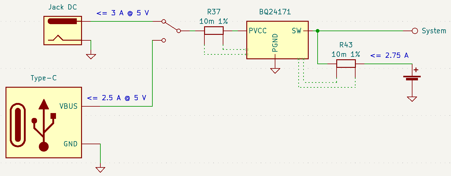
Pinebook Pro simplified charging schematics
When an external charger is connected, the battery charging process is automatically activated, it doesn’t depend on any software interactions and works all the same even with the main SoC powered down. The system automatically chooses between the barrel socket (limiting current draw to 3 A) and Type-C source (limited to 2.5 A), with the former preferred when both are connected at the same time (but the current limit is enforced as if Type-C was used).
The maximum charging current under normal conditions is limited to 2.75 A and the voltage to 4.35 V. Battery temperature affects these values, and if the measuring is done properly (see the section Battery temperature fix) the charge is fully suspended under 0 °C or above 60 °C, maximum current halved below 10 °C, maximum voltage reduced to 4.24 V above 45 °C and to 4.19 V above 50 °C.
The charging process automatically terminates when the voltage reaches the recharge threshold (upper limit - 0.1 V) ‘‘and’’ the current falls below 275 mA. However, this also stops supplying external power to the system, so if it’s running the battery voltage almost immediately drops below the recharge threshold, and the charging is turned on again.
Example run and charge time calculations
Assuming a fully charged 9600 mAh battery and an idle system using ‘‘performance’’ cpufreq governor with backlight at 3700/4095 consuming 9.6 W we can expect
9.6 Ah * 3.8 V / 9.6 W = 3.8 h
so that gives 3.8 hours of run time.
If the same battery is empty and a barrel plug charger is connected while system has the same load it will need
9.6 Ah * 3.8 V / ((3 A * 5 V * 0.9 - 9.6 W) * 0.95) = 9.85 h
that is 9.85 hours of charging from zero to full, assuming 0.9 DC-DC conversion efficacy and 0.95 charging efficacy.
Removing the system load reduces the time to
9.6 Ah * 3.8 V / (2.75 A * 3.8 V * 0.95) = 3.67 h
so if you need to fully charge the battery, e.g. before a trip, the fastest and most reliable way is to power down (not suspend) the system, leave the device with the charger connected for a few hours, upside down for better cooling, and wait for the red LED on the side to turn off.
Working without battery
With the battery disconnected the charger isn’t going to turn on, and the system won’t be getting any power from the external source. That’s why PBP has additional bypass cable that allows connecting external power directly to the system power bus. Of course it should be kept disconnected when the battery is present to avoid excess voltage overcharging and destroying the battery. It’s also recommended to add additional insulation to the cable connectors, as they expose battery and charger positive terminals on bare metal, and should never be accidentally connected to ground.
Hardware modifications
Type-C current limit
Since there’s no software control over the input current limit unmodified PBP always tries to draw up to 2.5 A from a Type-C charger.
It’s recommended to manually check /sys/class/power_supply/tcpm-source-psy-4-0022/current_max for all the chargers you’re using. When the value is lower than 2.5 A you shouldn’t use that charger with PBP as it would get overloaded, running out of specs.
If all of the chargers you want to use can supply 3 A or more ‘‘at 5 V’’ (the sysfs file will still report 2.5 A so check the official charger specs and/or label) consider lifting the limit to make it even with the barrel plug charger. For that remove the ‘‘R148’’ resistor on the bottom layer of the mainboard.
The easiest way is to use a soldering iron tip big enough to hold a 1 mm drop of an SnPb solder (it mixes with Pb-free nicely and lowers the melting point) to heat both sides of the resistor at once and lift it off.
Battery temperature fix
To ensure safe operation the charger IC is constantly monitoring the battery temperature with the sensor integrated inside the pack. The thermistor used is a 103AT NTC but the corresponding circuity on PBP mainboard was calculated for some other type. This results in the charger IC detecting 45 °C when the battery is in fact at just 35 °C, and 60 °C when the battery is at 46 °C. It’s easy to hit this threshold with heavy CPU or GPU loads as the metal back cover heats up from the SoC and slightly warms up the battery. Under these conditions the charging is suspended (with charging LED signalling a hardware issue), and the intensive tasks are continued on battery power alone, heating it up even more.
To fix this issue the resistor divider needs to be replaced to match the datasheet recommended values. For that one needs to change two 0402 resistors on the bottom side of the mainboard: use 2.2 kOhm 1 % for ‘‘R52’’ (instead of 4.4 kOhm installed by the factory), note it’s the one closer to the board edge; and 6.8 kOhm 1 % for ‘‘R54’’ (30 kOhm from the factory).
If your local hackspace doesn’t have suitable resistors consider getting a sample book from e.g. Aliexpress, it should cost less than 15 USD including shipping.
Troubleshooting
Tips, tricks and other information for troubleshooting your Pinebook Pro
If something has gone wrong, the key thing is remain calm and not do anything hasty and make things worse, particularly when flashing the eMMC or firmware. Try and make a record of all the things you did in the run-up to the problem (even to the point of using a camera to take a note of errors on the screen, this record can be vital later).
Manjaro Updates Fail With 404
If you have an old Manjaro installation then it will have the wrong repositories/mirrors set up and they won’t work. Set up new repositories by following these instructions: https://archived.forum.manjaro.org/t/another-mirror-transition-manual-intervention-required/132302
Power And Boot
New from the factory - Pinebook Pro won’t boot / power on
- Some Pinebook Pros came from the factory with the eMMC switch in the disabled position. It should be switched towards the back / hinge to enable the eMMC.
- The eMMC may have come loose during shipment. Open the back and verify that the eMMC is firmly seated.
- You may want to try unplugging the SD card daughterboard ribbon cable and see if it powers on (remove the battery and peel off a bit of the tape before unplugging it to avoid damage). If it does, try reseating it on both sides. It might have come loose during shipping.
- It’s possible that your eMMC is empty from the factory. Simply create a bootable SD card and see if your Pinebook Pro Getting started.
Pinebook Pro will not power on after toggling the eMMC enable/disable switch
- This may happen if you meant to toggle the UART/Headphone switch (9) towards touchpad for headphone use and instead you toggled the eMMC enable/disable switch (24).
- After reenabling eMMC by toggling switch (24) towards hinge, if Pinebook Pro does not turn on then press the RESET button (28). It is clearly marked ‘reset’ on the PCB board.
Pinebook Pro will not power on after removing and replacing EMI shielding
- Closely inspect that the shielding is firmly seated in the clips on all sides. You can be seated in the clips on one axis, and have missed on an another axis.
Pinebook Pro won’t boot when using UART console cable
- If you’re using the UART console cable from the Pine Store, you may want to see if it boots after you disconnect it. Some users report that custom-made cables based on FTDI UART adapters do not cause this issue.
- Make sure your USB to serial UART device is 3.3v. Many are 5v and some even +-12v. Pinebook Pro’s only support 3.3v and may act eratically when using higher voltage. Further, higher voltage could permananetly damage the Pinebook Pro’s SoC.
Pinebook Pro will not sleep with lid closed
A problem with the positioning of the lid magnet has been identified by several forum users in mid-2020 models of the Pinebook Pro. The magnetic field from the lid magnet operates a hall effect sensor located on the daughterboard (smallboard), which causes the Pinebook Pro to sleep when the lid is closed. If the magnet is not positioned correctly, the Pinebook Pro will not sleep when the lid is fully closed, but may sleep if the lid is open about an inch. If you experience this problem, repositioning of the magnet may be necessary.
Lid Magnet Repositioning Step-by-Step
Read these steps thoroughly before starting. This is a somewhat laborious process involving fragile parts!
- Remove bottom cover.
- Disconnect LCD and webcam ribbon cable from main board. Flip the small black strip on the connector upward and the ribbon cable can be easily removed. Do not pull the cable out without first raising the black retaining mechanism.
- Remove the small black plastic standoffs on each hinge and set aside.
- Remove the three screws from each hinge on the display assembly.
- Move the hinges upward to a 90 degree angle independently from the main body. Then lift the main body to the same 90 degree angle and you should be able to separate the display assembly from the main body. Set the main body aside.
- Remove the plastic hinge cover on the display assembly. There’s not really an easy way to do this, just work slowly and deliberately so as not to damage the sensitive cable inside. Start from either end and work your way inward. Use a small flathead screwdriver or similar tool to get started.
- Remove the hinges from the display assembly.
- Remove the rubber bumpers at the top corners of the display assembly to expose two screws. Remove the screws.
- Starting at the corners, separate the bezel from the lid. The clips that hold it in place are similar to those found on the hinge cover. Again, slow deliberate work will get it done. Work from the top down. Take care not to damage the cables in the bottom.
- With the bezel separated from the lid, feed the cable through the slot and set the bezel aside.
- Without removing the LCD panel completely, lift and move the panel slightly to the left, taking care not to damage the cable running underneath up to the webcam. This will give you room to remove the magnet without risking damage to the panel.
- The magnet is a silver colored bar near the bottom right side of the lid. Pry the magnet out with a small flathead or similar tool and set it aside. There is some adhesive but it’s not very strong.
- Put the LCD panel back where it belongs. Note the foam pads on either side of the panel. The magnet is the same width as the foam pad that keeps the panel in place, and should fit perfectly in the same channel.
- The magnet should be placed about 1 to 1.5cm lower than where it was originally. There should be no need for adhesive, as the magnet will stick to the LCD panel. For reference, the hall effect sensor that the magnet interacts with is in between the USB port and audio jack.
- Reassemble using these steps in reverse order.
Your Pinebook Pro should now sleep properly when the lid is closed.
Alternative Non-Invasive Lid Magnet Repositioning Method
- This method only takes a few seconds, and doesn’t require disassembling your Pinebook Pro:
- Turn on your Pinebook Pro so you can easily test when the internal magnet is in the correct position.
- Open the lid.
- Take a tiny 1/8" neodymium magnet, and place it along the right edge of the front bezel (LCD side) to locate the internal positioning magnet and discover the correct polarity. There should be one spot where it has the most attraction. Mark that spot.
- Using a very strong neodymium magnet(s) oriented with the same polarity you discovered using the tiny magnet, carefully place it on the spot you marked, and slowly slide it down the bezel until the internal magnet is pulled into the proper position. I successfully used four 1/2" cube neodymium magnets stacked on top of each other each having 20lbs of pull force to accomplish this.
- The internal magnet should be placed about 1 to 1.5cm lower than where it was originally. There should be no need for adhesive, as the magnet will stick to the LCD panel. For reference, the hall effect sensor that the magnet interacts with is in between the USB port and audio jack.
- Remove all external magnets, and test that the internal magnet is positioned correctly by slowly closing the lid while watching the LCD screen to make sure it stays suspended when closed, and wakes up when opened.
Your Pinebook Pro should now sleep properly when the lid is closed.
WiFi And Bluetooth
WiFi issues
- First, check the privacy switches to make sure your WiFi is enabled. They are persistant. See Privacy Switches
- Next, you may have to modify the
/etc/NetworkManager/NetworkManager.confas root user, and replacemanaged=falsewithmanaged=true. Then reboot. - If that doesn’t work, and if
dmesg | grep brcmfmacreports missing firmware, you will need to manually add the brcmfmac43455-sdio.* firmware files. This is due to a quiet change in the 2022 hardware revision. This repo has been tested and confirmed to work by no112. - For connections that drop and resume too often, it might be due to WiFi power management from earlier OS releases. Later OS releases either removed WiFi power management, or default to full power. (Power management can be turned off via command line with
iw dev wlan0 set power_save offoriwconfig wlan0 power off, although it is not persistent through re-boot.) - For connections that drop under load on the default Debian, remove
iwconfig wlan0 power offin the file/etc/rc.local. - If WiFi is un-usable or often crashes when using an alternate OS, then it might because its WiFi firmware is not appropriate for the WiFi chip in the Pinebook Pro. Try the latest firmware patch from https://gitlab.manjaro.org/tsys/pinebook-firmware/tree/master/brcm
- After re-enabling WiFi via the privacy switch, you have to reboot to restore function. There is a work around for the default Debian, (and may work with others);
sudo tee /sys/bus/platform/drivers/dwmmc_rockchip/{un,}bind <<< 'fe310000.dwmmc' - On extremely rare occasions, the WiFi antenna connection is loose. To fix, simply open up the bottom, re-connect the WiFi antenna cable. This may show up as any of the following symptoms:
- Can’t connect to any network, but the network manager software sees the WiFi device, (so it has not been disabled by the Privacy Switch)
- Very limited range, meaning you can make a connection if the Pinebook Pro is next to the WiFi router. But not the next room.
- Unreliable connections, that are also limited by range.
- Every once in a great while, the kernel will just fail to detect the wifi hardware (symptom: `ip link`` shows no wlan0). Only solution found so far is to hard-reset the machine (complete power-off then on again).
Bluetooth issues
- When connecting a Bluetooth device, such as a Bluetooth mouse, it does not automatically re-connect on re-boot. In the Bluetooth connection GUI, there is a yellow star for re-connect on boot. Use that button to enable a persistent connection. It can be changed back later.
- Bluetooth-attached speakers or headset require the pulseaudio-module-bluetooth package. If not already installed, it can be installed with a package manager or using the following:
sudo apt-get install pulseaudio-module-bluetooth - When using Bluetooth-attached speakers or headset and 2.4Ghz WiFi at the same time, you may experience stuttering of the audio. One solution is to use 5Ghz WiFi if you can. Or you may try using a different 2.4Ghz channel, perhaps channel 1 or the top channel, (11 in the USA, or 13/14 in some other countries).
Sound issues
- Many reports of no sound are due to the OS, incorrect settings, or other software problems (eg. PulseAudio). So first test to see if it is a software or hardware problem, by trying another OS via SD card. (For example, if Debian is installed on the eMMC, try Ubuntu on SD.)
- If you cannot get sound from the headphone jack, but can get sound from the speakers, then the headphone / UART console switch may be set to the UART mode. You can open the back and check the position of the switch. If set to UART mode, switch it to headphone mode. See the parts layout for the location and correct position of the switch.
- When using the USB C alternate DisplayPort mode, it is possible that the audio has been re-directed through this path. If your monitor has speakers, see if they work.
- See manjaro-arm/pinebookpro-post-install /var/lib/alsa/asound.state for some ALSA tweaks.
- See manjaro-arm/pinebookpro-audio for how to handle 3.5mm jack plug/unplug events with ACPID.
- Serveral users have reported that one internal speaker had reversed polarity. Thus, sound from the speakers is like an echo effect.
- There is a software fix using alsamixer and then enable either “R invert” or “L invert”, however, now the headphones have incorrect audio.
- The permanent fix is to re-wire one speaker, though this requires soldering small wires.
- Sound playback may be affected by the “mirroring” between the right and left channels, which results in distorted sound image. The root cause is the ALSA mixer setting named “DAC Stereo Enhancement”, which needs to be changed to 0% to fix this issue. Please see this forum post for further information.
NVMe SSD issues
Many Pinebook Pro users have reported issues with M.2 NVMe SSD drives, including random Linux lockups and crashes. Some of these issues are related to the RK3399’s errata that disables Gen2 (5 GT/s) speed for the PCI Express link used by the NVMe SSD, reducing it down to Gen1 speed (2.5 GT/s). However, Linux distributions that use Linux kernels older than version 5.12 still configure the PCI Express link to run at Gen2 speed, which requires manual reconfiguration to Gen1 speed in case system instability is experienced. See also this related discussion. This issue does not affect distributions with recent (newer than May 2021) kernels such as Manjaro ARM which seem to work with no modifications.
Some Pinebook Pro users have reported issues with the default settings for the APST (Autonomous Power State Transition) power saving, which cause an NVMe drive to disappear from the system or lock up after a certain period of time. Please see this forum thread for further information.
The output of the 3.3 V regulator inside the Pinebook Pro, which powers the M.2 SSD, becomes very noisy when the battery voltage drops below 3.9 V or so. This is a hardware issue of the Pinebook Pro that cannot be corrected without extensive hardware modifications, and it causes many M.2 SSDs to lock up under load and cause operating system crashes. The real trouble is that for some M.2 SSDs it takes a couple of hours of heavy I/O to lock up under these conditions, which may make them appear to be working reliably, while they eventually fail.
Keyboard and trackpad
Random Duplicated Key-Presses
Whether caused by an error in the Hailuck Keyboard firmware, or a physical defect in the membrane, the Pinebook Pro keyboard may randomly register some key-presses twice. The solution to this problem is trivial. Simply run the following command:
xkbset bouncekeys 20
If this return the following error:
bash: xkbset: command not found
Or some other similar error, you will need to install the command. It can most likely be found in your distro’s repository.
You may substitute some other value for 20 - this number denoting the time in milliseconds during which successive, duplicate key-presses will be rejected - with any value of your choice. If you are still receiving duplicates, consider increasing the number - perhaps by half. If you are consistently writing “aple”, try decreasing this number - perhaps by 25%.
Keys not registering / missing keys when typing
This issue occurs when your thumb or edge of the palm makes contact with left or right tip of the trackpad when you type. This is due to the palm rejection firmware being too forceful. Instead of only disabling the trackpad, so your cursor does not move all over the screen, it disables both the trackpad and the keyboard.
Using Fn+F7 to disable the touchpad will keep it from also disabling the keyboard.
A firmware update has been released to address this.
Key mapping
- See this /etc/udev/hwdb.d/10-usb-kbd.hwdb for some key mapping tweaks
Pinebook Pro gets stuck after first reboot in Trackpad Firmware Update
This refers to the firmware update shown here: https://github.com/dragan-simic/pinebook-pro-keyboard-updater#update-all-firmware-images
- If the system is not responding after the 1st reboot, it might be easiest to do a system restore or boot an SD-card-only OS, and follow up by running the second step of the trackpad firmware update with a USB keyboard and mouse plugged in
- System restore https://forum.pine64.org/showthread.php?tid=8229
- Firmware update https://github.com/dragan-simic/pinebook-pro-keyboard-updater#update-all-firmware-images
ANSI Fn + F keys wrong for F9, F10, F11 and F12
There appears to be a minor firmware issue for ANSI keyboard models of the Pinebook Pro. Some discussion and fixes have been proposed;
- Discussion thread Fn + F keys screwy for F9, F10, F11 and F12
- Proposed fix (ANSI) Fn + F(9-12) has wrong assignment after firmware update #14
USB docks & USB C alternate mode video
The Pinebook Pro uses the RK3399 SoC (System on a Chip). It supports a video pass through mode on the USB C port using DisplayPort alternate mode. This DisplayPort output comes from the same GPU used to display the built-in LCD.
Here are some selection criteria for successfully using the USB C alternate mode for video:
- The device must use USB C alternate mode DisplayPort. Not USB C alternate mode HDMI, or other.
- The device can have a HDMI, DVI, or VGA connector, if it uses an active translator.
- If USB 3 is also desired from a USB dock, the maximum resolution, frame rate and pixel depth is reduced to half the bandwidth. For example, 4K @ 30hz instead of 60hz.
- USB docks that also use USB C alternate mode DisplayPort will always have USB 2 available, (480Mbps, half-duplex).
Screen
Also see above about external screen using USB-C adaptor
After changing builtin LCD resolution, blank screen
Some people find that the text or icons are too small, so they attempt to change the resolution of the built-in display. Afterwards, the display is blank. Use the following to fix when logged into a text console as yourself, pressing Control-Alt-F1 through F6. After listing the resolutions, select the native resolution, (1920x1080 aka 1080p).
export DISPLAY=:0.0
xrandr -q
xrandr -s [resolution]
Once the screen resolution is restored, try using the software settings to configure the desired screen scaling.
If the above fix did not work, you can try this:
- Using a text console, (Control-Alt-F1), login with your normal user ID
- Edit the file
nano ~/.config/monitors.xml - Change the “width” value to “1920”
- Change the “height” value to “1080”
- If there is more than one monitor configuration listed, edit that one too. Be careful to make no other changes. If needed, exit without saving and re-edit.
- Save the file and exit.
- Login using the GUI and test
- If you are still logged in via the GUI, you will have to reboot using
sudo shutdown -r now. After the reboot, you should be able to login to the GUI login and have the resolution back to normal.
After restoring the usability of your Pinebook Pro’s graphical screen, also see this section on improving readability and usability.
Outer Shell
Cracks in the plastic
There have been multiple reports of cracks in the plastic keyboard and trackpad part of the case. These are generally near:
- Hinges
- USB ports
- Top side, around the corners
This seems to apply to the first batches in 2019. Later versions of the keyboard and trackpad have used better plastic. With replacements now in the Pine64 Store, it’s possible to simply order a replacement.
There have been a few reports of cracks in the plastic around the LCD display, but these appear to be less common. There are replacement LCDs with top cases available in the Pine64 Store.
Be extra careful if you open the PBP, the plastic parts of the shell, around the back corners or the hinges are really tiny and break easily.
UART
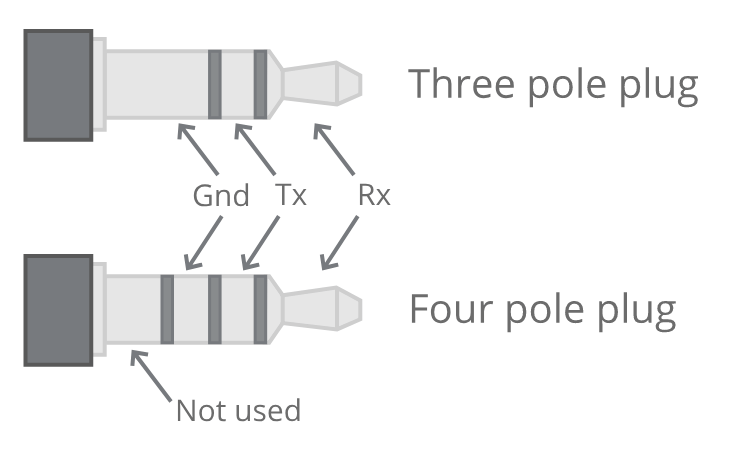
This shows signals from the Pinebook Pro’s point of view, so connect the adapter’s RX to ring 1, and TX to the tip. See also the Pine64 official document describing this.
Serial console UART is enabled by flipping the UART switch to the ON position (item 9). To do so, you need to remove the Pinebook Pro’s bottom cover by following the disassembly and reassembly guidelines. The OFF position is towards the touchpad, while the ON position is towards the display hinges.
With the UART switch in the ON position, the console is relayed via the headset jack, on which the audio output is no longer available. Please ensure that you are using a 3.3 V UART interface (such as the CH340, FTDI-232R, or PL2303, which are available in both 3.3 V and 5 V variants) to avoid damage to the RK3399 SoC. Older version of the serial console cable sold by the Pine Store used wrong voltage level and should not be used, see this forum thread for further information. Recent version of the same cable uses the right voltage level, which can also be checked by measuring the voltage on the TX ring.
Insert the USB plug of the cable into a USB port on the machine that you will use to monitor the Pinebook Pro’s serial console, ensuring that the audio jack of the serial cable is be fully inserted into the Pinebook Pro’s headphone port. Run lsusb in a terminal and you should see a line similar to this:
Bus 001 Device 058: ID 1a86:7523 QinHeng Electronics HL-340 USB-Serial adapter
Serial console output should now be accessible on the respective machine using a terminal emulator, such as screen, picocom or minicom. Here are a few examples of how to invoke a terminal emuator:
screen /dev/ttyUSB0 1500000picocom /dev/ttyUSB0 -b 1500000minicom -D /dev/ttyUSB0 -b 1500000
Features
Additional hardware
Hardware that is not part of the SoC.
Battery
- Lithium Polymer Battery (10,000 mAh; 9,600 mAh in later batches)
- Monitored by CW2015 which only measures the current voltage; reported state (charging/discharging), capacity (State-Of-Charge), remaining runtime and current are (poor) estimates
Display
- 14.0" 1920x1080 IPS LCD panel
Lid closed magnet
There is a magnet to detect when the laptop lid is closed, so action can be taken like sleep. This meets up with the Hall sensor on the daughter / small board to detect lid closed.
- The magnet is located on the LCD panel right side, around 1.5 inches up measure from bottom edge.
Webcam
- Internal USB attached Webcam
Audio
- 3.5mm stereo earphone/microphone plug
- Built-in microphone
- Built-in stereo speakers:
- Oval in design
- 3 mm high x 20 mm x 30 mm
Network
- WiFi:
- 802.11 b/g/n/ac
- Dual band: 2.4Ghz & 5Ghz
- Single antenna
- Bluetooth 5.0
Optional NVMe adapter
- PCIe 1.1, 2.5 GT/s per lane
- Note that due to errata, PCIe is limited to Gen1. See this commit.
- Four PCIe lanes, which can not be bifurcated, but can be used with one- or two-lane NVMe cards
- M keyed, though M+B keyed devices will work too
- Maximum length for M.2 card is 80mm (M.2 2280). The following sizes will also work: 2230, 2242, 2260
- Power: 2.5 W (continuous)
- Does not support SATA M.2 cards
- Does not support USB M.2 cards
Audio
ALSA configuration
If you do not have the integrated sound card selected as the default, create /etc/asound.conf with the following contents:
defaults.pcm.!card rockchipes8316c
defaults.ctl.!card rockchipes8316c
If you want to enable software mixing (dmix) by default for all ALSA apps (works without Pipewire or PulseAudio), make /usr/share/alsa/cards/simple-card.conf file contain this:
# default with dmix/dsnoop
simple-card.pcm.default {
	@args [ CARD ]
	@args.CARD {
		type string
	}
	type asym
	playback.pcm {
		type plug
		slave.pcm {
			@func concat
			strings [ "dmix:CARD=" $CARD ",RATE=44100" ]
		}
	}
	capture.pcm {
		type plug
		slave.pcm {
			@func concat
			strings [ "dsnoop:CARD=" $CARD ",RATE=44100" ]
		}
	}
}
Pop/click suppression workaround
If you’re annoyed by loud popping and clicking sounds, which occur a few seconds after the sound playback stops as a result of the components of the audio chain being turned on and off automatically by the Linux kernel, you can execute the following command manually, or automatically on boot using the tmpfiles.d systemd feature, for example:
echo 50 > /sys/kernel/debug/asoc/rockchip,es8316-codec/dapm_pop_time
This is a workaround because it effectively (ab)uses a built-in debugging feature of the Linux kernel’s audio subsystem, and one of the downsides is that a lot of messages are produced in the kernel log whenever the components of the audio chain are turned on and off automatically by the kernel.
Speaker polarity workaround
On newer Pinebook Pro batches, the inverted built-in speaker polarity issue has been fixed. On these units, the speaker polarity can be made reversed again by the alsa-ucm-conf package, which configures ALSA devices continuously. One workaround would be to remove the package, and the speaker polarity will no longer be set incorrectly. However, this also prevents the built-in speakers from being muted when an output device is plugged into the aux port.
Another workaround is to edit file /usr/share/alsa/ucm2/Rockchip/es8316/HiFi.conf and change all instances of R Invert to Normal. This is a workaround because it’s likely to be overwritten and lost if the alsa-ucm-conf package is updated.
Bluetooth and WiFi
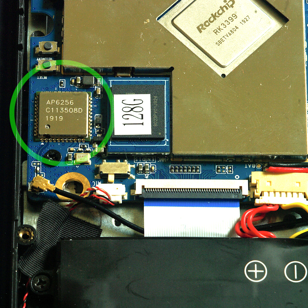
The Pinebook Pro’s AP6256 wireless module
Hardware Overview
The Pinebook Pro contains an AMPAK AP6256 wireless module to provide Wi-Fi (compliant to IEEE 802.11ac) and Bluetooth (compliant to Bluetooth SIG revision 5.0). The module contains a Broadcom transceiver IC, believed to be the BCM43456, as well as the support electronics needed to allow the Wi-Fi and Bluetooth modes to share a single antenna.
The wireless module interfaces with the Pinebook Pro’s system-on-chip using a combination of three interfaces: Bluetooth functionality is operated by serial UART and PCM, while the Wi-Fi component uses SDIO. It is unknown if the module’s Bluetooth capabilities are usable under operating systems that do not support SDIO.
The module’s RF antenna pin is exposed on the mainboard via a standard Hirose U.FL connector, where a coaxial feedline links it to a flexible adhesive antenna situated near the upper right corner of the Pinebook Pro’s battery. As the RF connector is fragile and easily damaged, it should be handled carefully during connection and disconnection, and should not be reconnected frequently.
Issues
Problems have been reported with the Wi-Fi transceiver’s reliability during extended periods of high throughput, especially on the 2.4 GHz band. While the cause of this has yet to be determined, switching to the 5 GHz band may improve stability.
Since the Bluetooth transceiver shares both its spectrum and antenna with 2.4 GHz Wi-Fi, simultaneous use of these modes may cause interference, especially when listening to audio over Bluetooth. If Bluetooth audio cuts out frequently, switching to the 5 GHz band – or deactivating Wi-Fi – may help.
Wi-Fi Capabilities
Wi-Fi on the Pinebook Pro is capable of reaching a maximum data transfer rate of approximately 433 megabits per second, using one spatial stream. The transceiver does not support multiple spatial streams or 160-MHz channel bandwidths.
The Wi-Fi transceiver supports the lower thirteen standard channels on the 2.4 GHz band, using a bandwidth of 20 MHz. At least twenty-four channels are supported on the 5 GHz band, spanning frequencies from 5180 to 5320 MHz, 5500 to 5720 MHz, and 5745 to 5825 MHz, with bandwidths of 20, 40, or 80 MHz. This might vary depending on the country you specify in the wireless settings, see iw reg get; iw list.
Maximum reception sensitivity for both bands is approximately -92 dBm. The receiver can tolerate input intensities of no more than -20 dBm on the 2.4 GHz band, and no more than -30 dBm on the 5 GHz band. Maximum transmission power is approximately +15 dBm for either band, falling further to approximately +10 dBm at higher data transfer rates on the 5 GHz band.
With current available drivers and firmware, the Wi-Fi interface supports infrastructure, ad-hoc, and access-point modes with satisfactory reliability. Monitor mode is not presently supported. Wi-Fi Direct features may be available, but it is unclear how to make use of them under Linux.
Be aware that Linux userspace utilities, such as iw, may report inaccurate information about the capabilities of wireless devices. Parameter values derived from vendor datasheets, or direct testing, should be preferred to the outputs of hardware-querying tools. That said, if a certain feature is not reported by iw it means the currently running kernel driver plus firmware combination doesn’t support it, even when the hardware is capable.
WPA3 PSK support should be possible with iwd but not wpa_supplicant, see this ticket for details.
Bluetooth Capabilities
Bluetooth data transfer speeds have an indicated maximum of 3 megabits per second, but it is unclear what practical data rates can be expected. Audio streaming over Bluetooth is functioning normally, as is networking. Bluetooth Low-Energy functions, such as interacting with Bluetooth beacons, have not yet been tested conclusively.
The Bluetooth transceiver supports all 79 channel allocations, spanning frequencies from 2402 MHz to 2480 MHz. Reception sensitivity is approximately -85 dBm, with a maximum tolerable reception intensity of -20 dBm. Bluetooth transmission power is limited to +10 dBm.
Disabling Bluetooth
To disable Bluetooth under Linux once:
sudo rfkill block bluetooth
To confirm if Bluetooth under Linux is disabled:
rfkill
To disable Bluetooth on boot (NOTE: for distributions such as Manjaro XFCE see the step below):
sudo systemctl enable rfkill-block@bluetooth
To disable Bluetooth on certain distributions, such as Manjaro XFCE, right click on the Bluetooth panel icon, select plugins, then PowerManager, then configuration and then deselect the auto power on option
Bootable storage
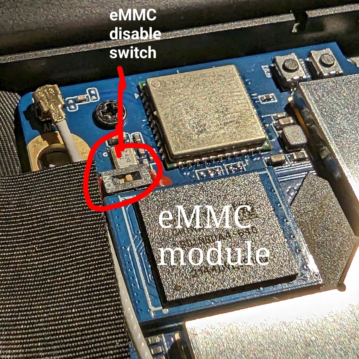
The PineBook Pro eMMC module and switch, shown in ’enabled’ position
Boot sequence details
The RK3399’s mask 32KB ROM boot code looks for the next stage of code at byte off-set 32768, (sector 64 if using 512 byte sectors). This is where U-Boot code would reside on any media that is bootable, RK3399 boot sequence
Boot devices
The Pinebook Pro is capable of booting from eMMC, USB 2.0, USB 3.0, or an SD card. It cannot boot from USB-C. The boot order of the hard-coded ROM of its RK3399 SoC is: SPI NOR, eMMC, SD, USB OTG.
At this time, the Pinebook Pro ships with a Manjaro + KDE build with u-boot on the eMMC. Its boot order is: SD, USB, then eMMC.
(An update has been pushed for the older Debian + MATE build that improves compatibility with booting other operating systems from an SD card. In order to update, fully charge the battery, establish an internet connection, click the update icon in the toolbar, and then reboot your Pinebook Pro. Please see this log for details.)
Please note that PCIe, the interface used for NVMe SSD on the Pinebook Pro, is not bootable on the RK3399 and therefore is not a part of the boot hierarchy. It is possible to run the desired OS from NVMe by pointing extlinux on the eMMC to rootfs on the SSD. This requires U-Boot, the Kernel image, DTB, and extlinux.conf in a /boot partition on the eMMC.
eMMC information
The eMMC appears to be hot-pluggable. This can be useful if trying to recover data or a broken install. Best practice is probably to turn the eMMC switch to off position before changing modules. Note that the enable/disable label on the silkscreen is incorrect on some board revisions (known bad on v2.1).
The eMMC storage will show up as multiple block devices:
- mmcblk1boot0 - eMMC standard boot0 partition, may be 4MB
- mmcblk1boot1 - eMMC standard boot1 partition, may be 4MB
- mmcblk1rpmb - eMMC standard secure data partition, may be 16MB
- mmcblk1 - This block contains the user areas
Only the last is usable as regular storage device in the Pinebook Pro. The device number of “1” shown above may vary, depending on kernel.
If the eMMC module is enabled after boot from an SD card, you can detect this change with the following commands as user “root”:
echo fe330000.mmc >/sys/bus/platform/drivers/sdhci-arasan/unbind
echo fe330000.mmc >/sys/bus/platform/drivers/sdhci-arasan/bind
(Note: with the device trees coming with older kernels (Linux < 5.11), the device name may be fe330000.sdhci instead of fe330000.mmc)
External ports list
Here are a list of the external ports. See Technical Reference - Expansion Ports for port specifications.
- Left side
- Barrel jack for power, (with LED)
- USB 3, Type A
- USB 3, Type C
- Right side
- USB 2, Type A
- Standard headset jack
- MicroSD card slot
Internal layout
Main chips
- RK3399 system-on-chip (1)
- LPDDR4 SDRAM (21)
- SPI NOR flash memory (29)
- eMMC flash memory module (26; Note: Some datasheets indicate a low supported number of mating cycles.)
- WiFi/BT module (27)
Mainboard Switches and Buttons
There are two switches on the main board: disabling the eMMC module (24), and enabling serial console UART (9) via headphone jack.
The Reset and Recovery buttons (28): the reset button performs an immediate reset of the laptop. The Recovery button is used to place the device in maskrom mode. This mode allows flashing eMMC using Rockchip tools (e.g. rkflashtools).
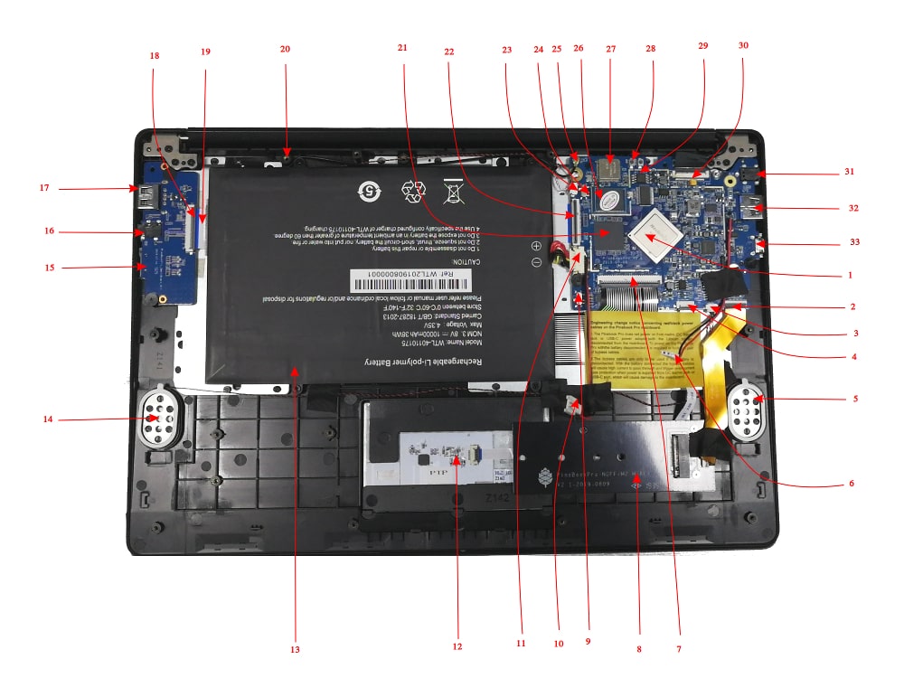
Key Internal Parts
| Number | Type | Descriptor |
|---|---|---|
| 1 | Component | RK3399 System-On-Chip |
| 2 | Socket | PCIe x4 slot for optional NVMe adapter |
| 3 | Socket | Speakers socket |
| 4 | Socket | Touchpad socket |
| 5 | Component | Left speaker |
| 6 | Connector | Power bridge connector |
| 7 | Socket | Keyboard Socket |
| 8 | Component | Optional NVMe SSD adapter |
| 9 | Switch | UART/Audio switch - enables serial console UART via headphone jack |
| 10 | Socket | Power bridge socket |
| 11 | Socket | Battery socket |
| 12 | Component | Touchpad |
| 13 | Component | Battery |
| 14 | Component | Right speaker |
| 15 | Socket | MicroSD card slot |
| 16 | Socket | Headphone / serial console UART jack |
| 17 | Socket | USB 2.0 Type A |
| 18 | Socket | Daughterboard-to-mainboard ribbon cable socket |
| 19 | Cable | Daughterboard-to-mainboard ribbon cable |
| 20 | Component | microphone |
| 21 | Component | LPDDR4 RAM |
| 22 | Socket | Mainboard-to-daughterboard ribbon cable socket |
| 23 | Socket | Microphone socket |
| 24 | Switch | Switch to hardware disable eMMC |
| 25 | Antenna | BT/WiFI antenna |
| 26 | Component | eMMC flash memory module |
| 27 | Component | BT/WiFi module chip |
| 28 | Buttons | Reset and recovery buttons |
| 29 | Component | SPI flash storage |
| 30 | Socket | eDP LCD socket |
| 31 | Socket | Power in barrel socket |
| 32 | Socket | USB 3.0 Type A |
| 33 | Socket | USB 3.0 Type C |
Smallboard detailed picture
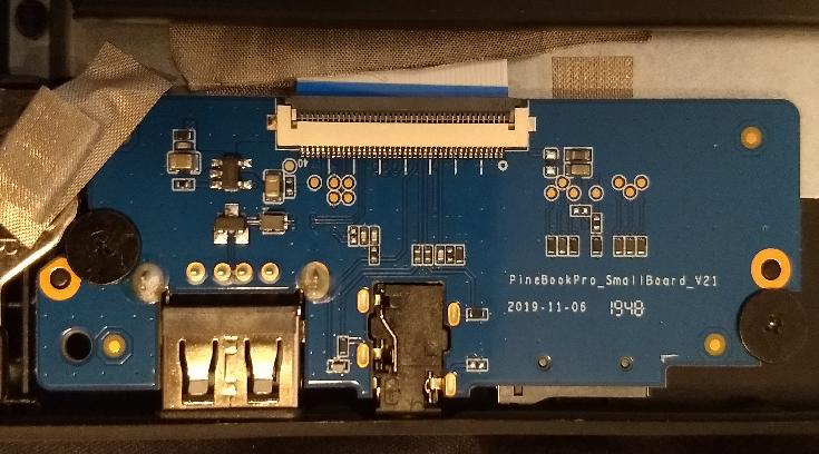
LCD panel
- Model: BOE NV140FHM-N49
- 14.0" (35.56 cm) diagonal size
- 1920x1080 resolution
- 60 Hz refresh rate
- IPS technology
- 1000:1 contrast
- 250 nit brightness
- 63% sRGB coverage
- 6-bit color
- 30-pin eDP connection
LEDs
In total, there are four LEDs on the Pinebook Pro, three of which are placed in the top-left side of the keyboard, and one near the barrel port:
- The red LED next to the barrel port indicates charging, in three ways. First, it will illuminate steadily when either the barrel jack power supply or a USB Type-C charger is connected to the Pinebook Pro, and the charging is active (that means power is supplied to the battery and system in parallel, and if it’s not enough the battery can still be discharging). Second, if the battery is at 100 %, the LED will remain turned off regardless of the connected power input (however, this is not possible for more than a split-second when the system is running). Third, this LED will flash at 0.5 Hz if there are any problems that prevent charging, such as the battery becoming too hot. To fully understand all the nuances, read the Power and charging article.
- The power indicator LED, above the keyboard, supports three different colors: green, amber and red. It is also capable of flashing to indicate eMMC activity, with proper software support. In the default Debian with MATE build, green LED means power and red means suspend (amber is unused).
- The green NumLock LED, above the keyboard.
- The green CapsLock LED, above the keyboard.
The NumLock and CapsLock LEDs serve their usual purposes on a keyboard, but they also have a secondary function. When the privacy switches get activated they blink to confirm that the switch has been activated.
Microphones
While it has been said that some Pinebook Pro units contain only one microphone despite having two labeled microphone holes on the outer casing, other units do indeed contain two microphones. It is presently unclear which batches have either configuration. Units from the initial community batch of 1000 units (following the initial 100) are believed to contain two, populating both labeled holes.
The wires leading to both microphones connect to the mainboard with a small white plastic connector, located directly adjacent to the ribbon cable attachment point for the keyboard interface.
Built-in microphones not working
If pavucontrol input doesn’t show microphone activity try changing the privacy switches. If the switches are in the correct place and microphone input isn’t working you can run alsamixer from the command line, hit F6 and select the es8316, hit F4 to get to the capture screen, select the bar labeled ADC, increase the gain to 0 dB, change the audio profile in pavucontrol to another one with input. Additionally you may want to modify ADC PGA to get the levels to where you want them. If that still hasn’t fixed it you may want to check that the microphone connector is plugged in.
External wired microphone not working
If you connect a headset with a microphone, you might need to open alsamixer, change card to es8316, and change option Differential Mux from lin1-rin1 to lin2-rin2.
Power supply
- Input Power: 5V DC, 15W (current limit 3A)
- Mechanical: 3.5mm OD / 1.35mm ID, Barrel jack
- USB-C 5V, 12.5W (current limit is at 2.5A regardless of the USB PD negotiations result)
- Only use one power input at a time, barrel jack OR USB-C (note: some powerful Type-C adapters have rather limited current for 5 V operation, and e.g. 2 A won’t be enough to run the system and charge the battery at the same time, so check the specs)
SPI
The Pinebook Pro comes equipped with two non-volatile storage components, the eMMC and the SPI. The capacity of the SPI is 128Mbit (16MiB) and it may be used in the boot process.
Boot data can be written to the SPI via two methods: either from within PBP or from a second machine connected to the PBP by USB.
Writing to SPI from within PBP
Forum user pcm720 provided an example of writing to the SPI from within Linux in their self-published version of U-Boot that offers boot functionality for NVMe drives. It involves use of flash_erase command (available in the mtd-utils package on Arch/Manjaro) and the dd command.
However, flashcp command should be used instead of dd, to make sure all specifics of the underlying flash memory are covered.
Writing to SPI from a second machine
Writing to the SPI from a second machine is more complicated than the other method, but it is the only option when troubleshooting an SPI flash gone wrong. This method works by bringing the RK3399 SoC into maskrom mode and issuing commands on the second machine that download the flash image onto the Pinebook Pro.
Upon entering maskrom mode, the power LED on your Pinebook Pro won’t light up and neither will the display. Instead, your second machine, the one connected to your Pinebook Pro via USB, will indicate maskrom mode by logging to journalctl.
There are two ways to reach maskrom mode, but the first tends to be less reliable.
Maskrom mode (unreliable method)
According to Rockchip documentation, these steps should work; unfortunately, many users have reported them to be unsuccessful. You may need to repeat these steps several times for them to work.
- Press and hold recovery button.
- Short press reset.
- Release recovery button after about three seconds.
In case this approach fails, please see the section below for a more reliable method.
Maskrom mode (reliable method)
- Build and install
rkdeveloptool(see project repository for instructions) - Verify successful installation. Running
rkdeveloptool --versionshould output:rkdeveloptool ver 1.3 - Run
journalctl -fand keep it running. Once the Pinebook Pro is connected and maskrom mode is reached it will produce additional output. - Power off the Pinebook Pro.
- Unscrew the bottom cover.
- Remove the metal RF shield surrounding the main CPU. The shield is held in place small clamps on the board. The clamps can be released with a pry tool and some force. This forum post with photos shows how it can be done.
- Disconnect all boot devices, i.e. eMMC, microSD card and USB.
- Locate SPI flash (component number 29 on this photo of the Pinebook Pro internals).
- Connect your Pinebook Pro with USB-C to USB-A cable to second machine (Pinebook Pro on the USB-C side)
- Short pins CLK and VSS (see chip diagram to the right for the names of pins). This can be done with a pair of tweezers when short on tools.
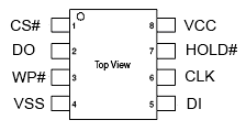
right
- Power on the Pinebook Pro.
- Press the reset button (component number 28).
- Check if there is new output from
journalctlprogram. - Check if the Pinebook Pro is connected by running
rkdeveloptool ld. If successful, the output should be like:DevNo=1 Vid=0x2207,Pid=0x330c,LocationID=1401 Maskrom
After entering maskrom mode
Now that when the RK3399 SoC is in maskrom mode, you can use rkdeveloptool to write data to the SPI. To do so you’ll need the binary file you’ll be writing to SPI, which will be referred to as SPI_new.bin, and a helper file named rk3399_loader_spinor_v1.15.114.bin.
- Flash the flash helper db file:
rkdeveloptool db rk3399_loader_spinor_v1.15.114.bin. If successful, the output should readDownloading bootloader succeeded. - Flash the new SPI binary:
rkdeveloptool wl 0 SPI_new.bin. If successful, the output should read:Write LBA from file (100%). - Test the installation:
rkdeveloptool td. If successful, output should readReset Device OK. - Run
rkdeveloptool rdto reboot your Pinebook Pro.
Zeroing out the SPI
In case, you wrote something bad to your SPI, it’s helpful to wipe away that data with zeros. To do that, you follow the same steps above to enter maskrom mode and then write a binary file that consists of all zeros.
- Create the binary file
dd if=/dev/zero of=zero.bin bs=1M count=16 - Flash the flash helper db file:
rkdeveloptool db rk3399_loader_spinor_v1.15.114.bin. If successful, the output should readDownloading bootloader succeeded. - Flash the new SPI binary:
rkdeveloptool wl 0 zero.bin. If successful, the output should read:Write LBA from file (100%). - Test the installation:
rkdeveloptool td. If successful, output should readReset Device OK. - Run
rkdeveloptool rdto reboot your Pinebook Pro.
Touchpad
Documentation for the touchpad can be found in Datasheets for Components and Peripherals. It is the only component of the Pinebook Pro held in place with strong adhesive tape. Here are some of its features:
- 2 actuating buttons.
- multi-touch functionality.
- A matte finish that your finger can slide along easily.
- A reasonable size (96 mm × 64 mm; diagonal: 115.378 mm or 4.542 inches).
Troubleshooting
If you are having trouble using 2 fingers to scroll or emulate the click of a mouse’s right-button, then try these solutions:
- Update the firmware.
- Keep your 2 fingers spread apart rather than close together.
- Individual programs might need to be configured specially. *. For smooth scrolling and gestures under X-Windows, Firefox should be launched with with the following environment variable assignment:
MOZ_USE_XINPUT2=1
- Experiment with other settings, via X-Windows Configuration or some other system preferences. For example, you could disable double-finger scrolling, and instead enable scrolling by sliding one finger along the edge of the touchpad.
Firmware
The touchpad controller is connected to the keyboard controller. All touchpad events go through the keyboard controller and its software, then to the keyboard controller’s USB port. Note that the touchpad does have separate firmware (which has to be written through the keyboard controller). The touchpad vendor’s firmware binary can be flashed from userspace using the following open source command-line utility:
- Kamil Trzciński’s pinebook-pro-keyboard-updater.
Naturally, forks have begun to appear:
- Jack Humbert’s fork
- Dragan Simic’s fork. This one has recently delivered a much improved firmware from the vendor one, which greatly improves the control of the cursor (see this thread for discussion). Before installing this update, consider resetting to the defaults any configuration of your touchpad.
All Pinebook Pros shipped from the factory have the old buggy version installed so consider updating the keyboard and touchpad firmware with the latest fixes from Dragan.
Before updating any firmware, your Pinebook Pro should be either fully charged or, preferably, running from mains. This utility will be writing data to chips on the keyboard and touchpad, so a loss of power during any stage of the update can result in irrecoverable damage to your touchpad or keyboard.
The scripts ought to work on all operating systems available for the Pinebook Pro. Some operating systems may however, require installation of relevant dependencies. The instructions below assume a Debian desktop. To install these dependencies, newer Pinebook Pro models that come with Manjaro will require a different command.
There are two keyboard versions of the Pinebook Pro: ISO (vertical Enter key) and ANSI (horizontal Enter key). You need to know which model you have prior to running the updater.
Firmware update steps for both models are listed below.
What you will need:
- Connection to internet for getting dependencies, either through Wi-Fi or wired ethernet (USB dongle).
- Your Pinebook Pro fully charged or running from mains power.
- An external USB keyboard and mouse (or access to the Pinebook Pro via SSH. Please note that for some configurations, the SSH service might not be available without first having logged in once. In this case, you will definitely want at least an external keyboard or UART serial console).
ISO Model
From the terminal command line:
Debian-based distributions:
git clone https://github.com/dragan-simic/pinebook-pro-keyboard-updater
cd pinebook-pro-keyboard-updater
sudo apt-get install build-essential libusb-1.0-0-dev xxd
make
Arch-based distributions (note: build-essential, xxd are named differently. Arch linux does not split its packages as foo and foo-dev):
git clone https://github.com/dragan-simic/pinebook-pro-keyboard-updater
cd pinebook-pro-keyboard-updater
sudo pacman -Syu base-devel xxd-standalone libusb
make
The next steps are identical for both Debian and Arch distros.
Step 1
cd pinebook-pro-keyboard-updater
sudo ./updater step-1
sudo poweroff # do not use 'reboot'
Step 2 (after booting)
cd pinebook-pro-keyboard-updater
sudo ./updater step-2 iso
sudo poweroff # do not use 'reboot'
ANSI Model
From the terminal command line:
Debian-based distributions:
git clone https://github.com/dragan-simic/pinebook-pro-keyboard-updater
cd pinebook-pro-keyboard-updater
sudo apt-get install build-essential libusb-1.0-0-dev xxd
make
Arch-based distributions (note: build-essential, xxd are named differently. Arch linux does not split its packages as foo and foo-dev):
git clone https://github.com/dragan-simic/pinebook-pro-keyboard-updater
cd pinebook-pro-keyboard-updater
sudo pacman -Syu base-devel xxd-standalone libusb
make
The next steps are identical for both Debian and Arch distros.
Step 1
cd pinebook-pro-keyboard-updater
sudo ./updater step-1
sudo poweroff # do not use 'reboot'
Step 2 (after booting)
cd pinebook-pro-keyboard-updater
sudo ./updater step-2 ansi
sudo poweroff # do not use 'reboot'
When done, if some of the keys produce incorrect characters, please check your OS’s language settings. For ANSI users, the default OS may have shipped with English UK as the default language. You can change it to English US if desired.
Revised Firmware
In addition, you might consider using revised firmware data. This is one final step that should not require a reboot:
Step 3: ISO (after booting)
sudo ./updater flash-kb firmware/default_iso.hex
Step 3: ANSI (after booting)
sudo ./updater flash-kb firmware/default_ansi.hex
X Window System Configuration
When using X.Org display server the touchpad can be handled either by libinput or synaptic input drivers. The former allows to have shared configuration for both X.Org and Wayland but the latter provides more tunables (e.g. configurable edge scrolling, circular scrolling, mapping of multi-touch events to mouse buttons etc.).
Some forum members have found that an adjustment to X11 will allow finer motion in the touchpad. If you use the synaptic mouse/touchpad driver, use this command to make the change live:
synclient MinSpeed=0.2
You may experiment with different settings, but 0.25 was tested as helping noticeably.
To make the change persist across reboots, change the file /etc/X11/xorg.conf similar to below:
Section "InputClass"
        Identifier "touchpad catchall"
        Driver "synaptics"
        MatchIsTouchpad "on"
        MatchDevicePath "/dev/input/event*"
        *Option "MinSpeed" "0.25"*
EndSection
The line “Option “MinSpeed” “0.25"” is changed here.
Another forum user built on the above settings a little, and have found these to be very good:
synclient MinSpeed=0.25
synclient TapButton1
synclient TapButton2=3
synclient TapButton3=2
synclient FingerLow=30
synclient PalmDetect=1
synclient VertScrollDelta=64
synclient HorizScrollDelta=64
FingerLow has the same value as ‘FingerHigh’ in one config (30). It is believed to help reduce mouse movement as you lift your finger, but it’s unknown whether synaptic works like this. You may find this config to be comfortable for daily use.
TabButton allows to just tab the touchpad instead of physically pressing it down (to get this click noise).
The right mouse click is emulated by tapping with two fingers on the touchpad. If you feel that this is not very responsive you can try this value:
synclient MaxTapTime=250
Some users may encounter an issue with the mouse jumping when typing when using libinput driver due to their hand hitting the touchpad which can be fixed by updating the X.Org settings to disable it while typing. One can disable the touchpad while typing by setting the below option in the X.Org config simliar to the previous example.
Option "DisableWhileTyping" "on"
The setting can be verified by using the xinput command to first list the devices and then listing the properties for the touchpad device. Exact commands to check this have been omitted for save of brevity. If DisableWhileTyping is shown enabled but does not appear to be working the issue may be due to the fact that the keyboard is connected to a USB bus which causes it to be seen as a external keyboard. Make sure you have libinput version 1.19.0 or later installed as it includes the necessary quirk.
Synaptic driver users can add syndaemon to their X11 session for the same effect.
Webcam
Streaming video resolutions supported, (uncompressed):
- 320 x 240
- 640 x 480
- 800 x 600
- 1280 x 720
- 1600 x 1200
Still frame resolutions supported:
- 160 x 120
- 176 x 144
- 320 x 240
- 352 x 288
- 640 x 480
- 800 x 600
- 1280 x 720
- 1600 x 1200
Keyboard
The Pinebook Pro is available in two keyboard configurations: ISO and ANSI. Both the keyboard and touchpad in the Pinebook Pro use the USB 2.0 protocol and show up as such in xinput. The keyboard features function (Fn) keys in the F-key row, which include display brightness controls, sound volume, touchpad lock, and other functionality. There is also a custom PINE64 logo key that functions as Menu/Super key. It has also a secondary functionality for setting the privacy switches.
The keyboard firmware binary can be flashed from userspace using the provided open source utility.
Documentation for the keyboard can be found in Datasheets for Components and Peripherals and details regarding the assembly can be found under Keyboard assembly.
Typing special characters
The UK ISO Layout does not have dedicated keys for characters like the German umlauts (Ä, Ö, Ü, etc). Certain characters can still be generated by means of either key combinations or key sequences.
| Character | Key combination/sequence |
|---|---|
| Ä, Ö, Ü, ä, ö, ü | AltGr + [ followed by A, O, U, a, o or u |
| µ | AltGr + m |
| Ø, ø | AltGr + O, AltGr + o |
| @ | AltGr + q (as on the German layout) |
| ß | AltGr + s |
| § | AltGr + S |
| ° | AltGr + ) |
Privacy Switches
There are three privacy switches mapped to the F10, F11 and F12 keys on the Pinebook Pro keyboard. They de/activate the following:
Privacy switch function and description
| Combination | Effect | Description | Notes |
|---|---|---|---|
| PINE64 logo key+F10 | Microphone Privacy switch | CAPs lock LED blinks. 2 blinks = enabled, 3 blinks = disabled | |
| PINE64 logo key+F11 | WiFi Privacy switch | NUM lock LED blinks. 2 blinks = WiFi enabled / privacy switch disabled, 3 blinks = WiFi disabled / privacy switch enabled. | Re-enabling requires reboot (or a command line hack to bind/unbind). |
| PINE64 logo key+F12 | Camera privacy switch | CAPs lock and NUM lock LEDs blink together. 2 blinks = enabled, 3 blinks = disabled | Can use tools like lsusb to detect camera’s presence. If not detected, check privacy switch. |
The keyboard operates on firmware independent of the operating system. It detects if one of the F10, F11 or F12 keys is pressed in combination with the Pine key for 3 seconds. Doing so disables power to the appropriate peripheral, thereby disabling it. This has the same effect as cutting off the power to each peripheral with a physical switch. This implementation is very secure, since the firmware that determines whether a peripheral gets power is not part of the Pinebook Pro’s operating system. So the power state value for each peripheral cannot be overridden or accessed from the operating system. The power state setting for each peripheral is stored across reboots inside the keyboard’s firmware flash memory.
Basic summary of replacing keyboard
This guide is very basic and should be fleshed out with (better) pictures. There just isn’t a list of steps anywhere else yet.
Here’s what the replacement keyboard looks like:
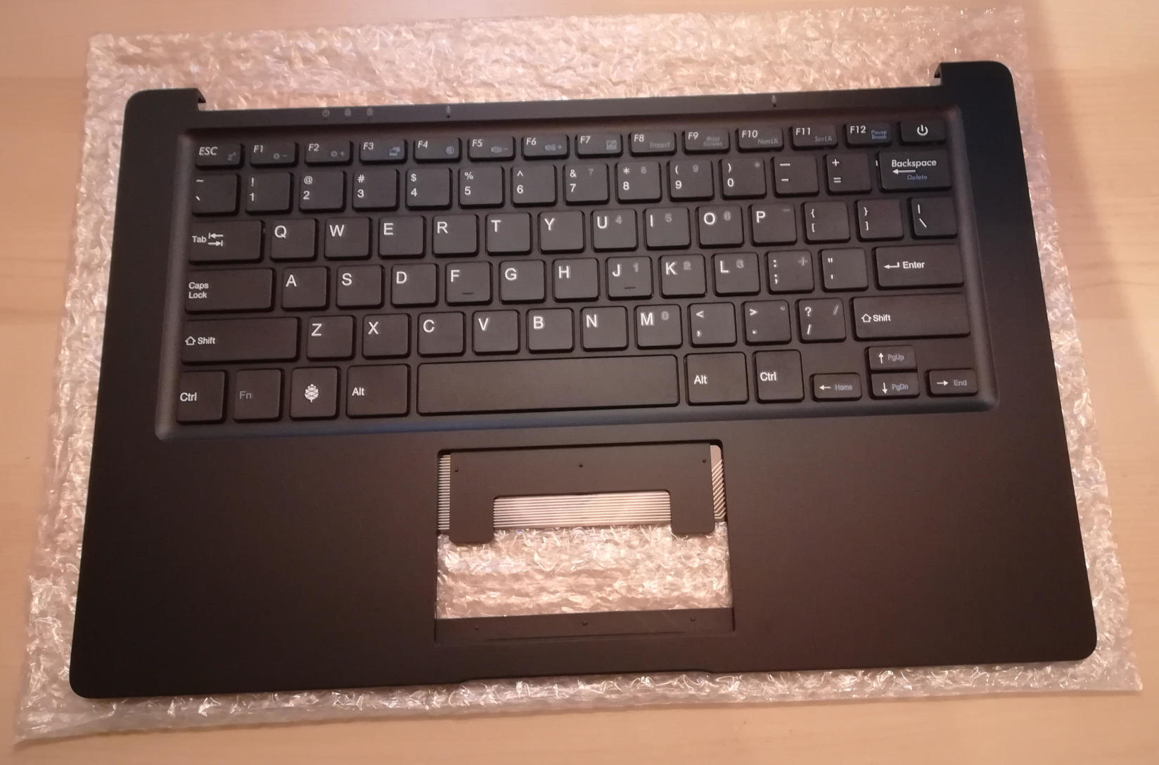

Step 0: If changing from ISO keyboard to ANSI keyboard, or vice versa, be sure to have a system capable of running the firmware updater that you can access either remotely or with a USB keyboard beyond the internal keyboard, as the firmware for each is very different and keys won’t work correctly. See https://forum.pine64.org/showthread.php?tid=8407 (and for NetBSD, https://forum.pine64.org/showthread.php?tid=8716).
Step 1: The remove back back panel.
There are 10 screws on the back that must be removed, and the back panel detached. I recommend using a PH0 bit. The speakers may remain attached via glue to the case and should be carefully pried off. When this is done, taking photos of how everything looks now can help put it all back together later.
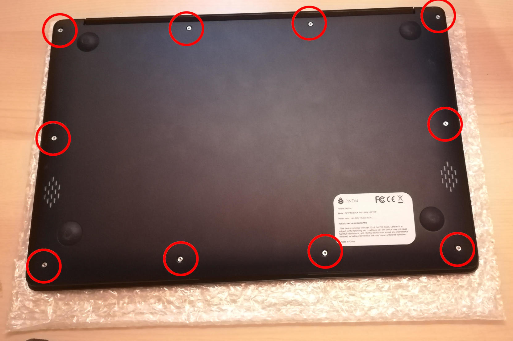
Step 2: Places to unscrew.
There are 3 items screwed into the keyboard frame that must be removed. There are 2 large screws for daughter board, 3 large screws and 1 small screw for mainboard, and 4 small screws for battery. Be sure to not lose them. I recommend a PH00 bit for the large screws on the daughter and main boards and a PH1 bit for the small screws on the battery and mainboard.
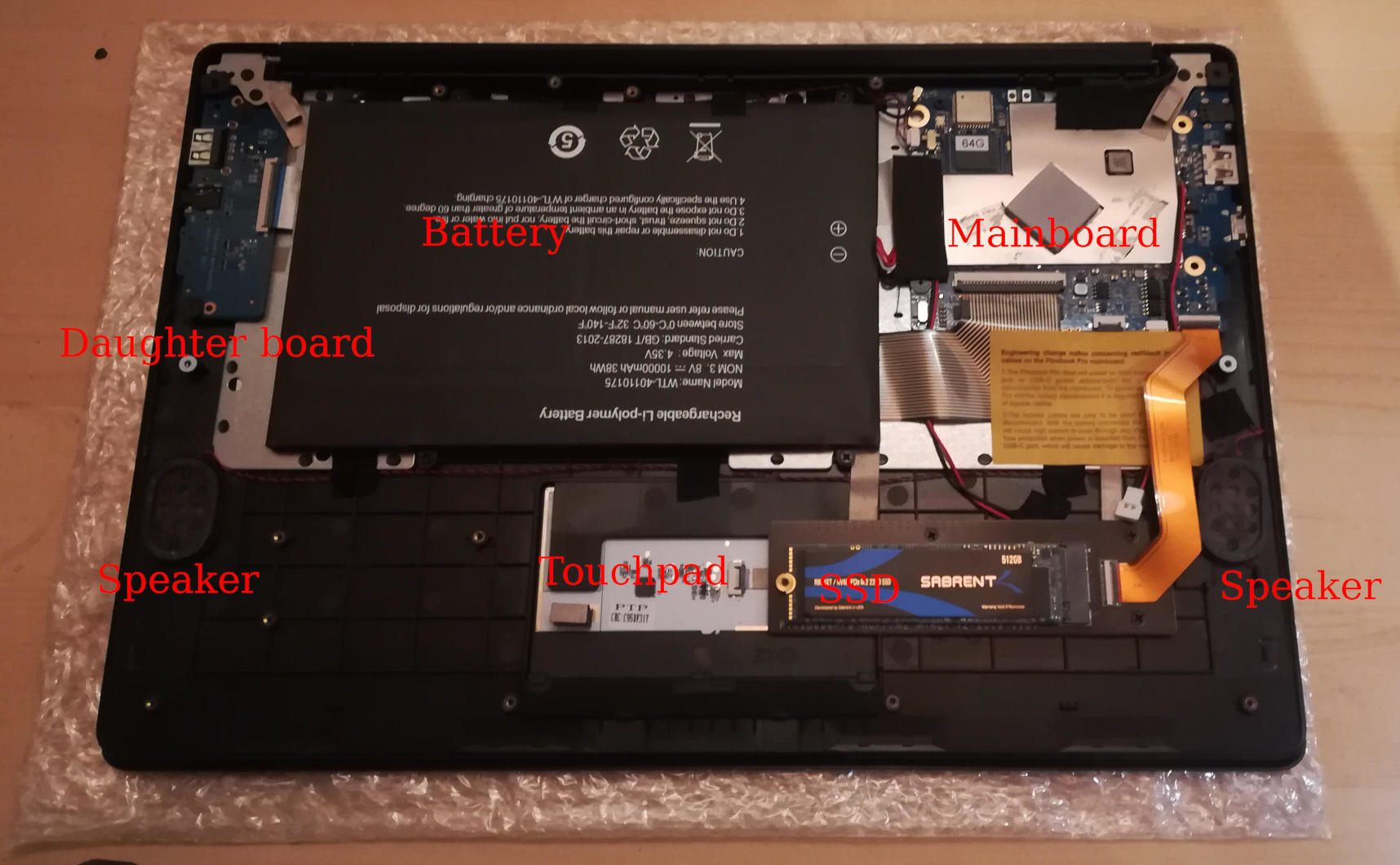
Step 3: Remove the battery.
Once the battery screws are removed, it should be unplugged from the mainboard and removed. Note that there are two unconnected cables lying around, that should remain unconnected. They are used when the battery is disconnected entirely.
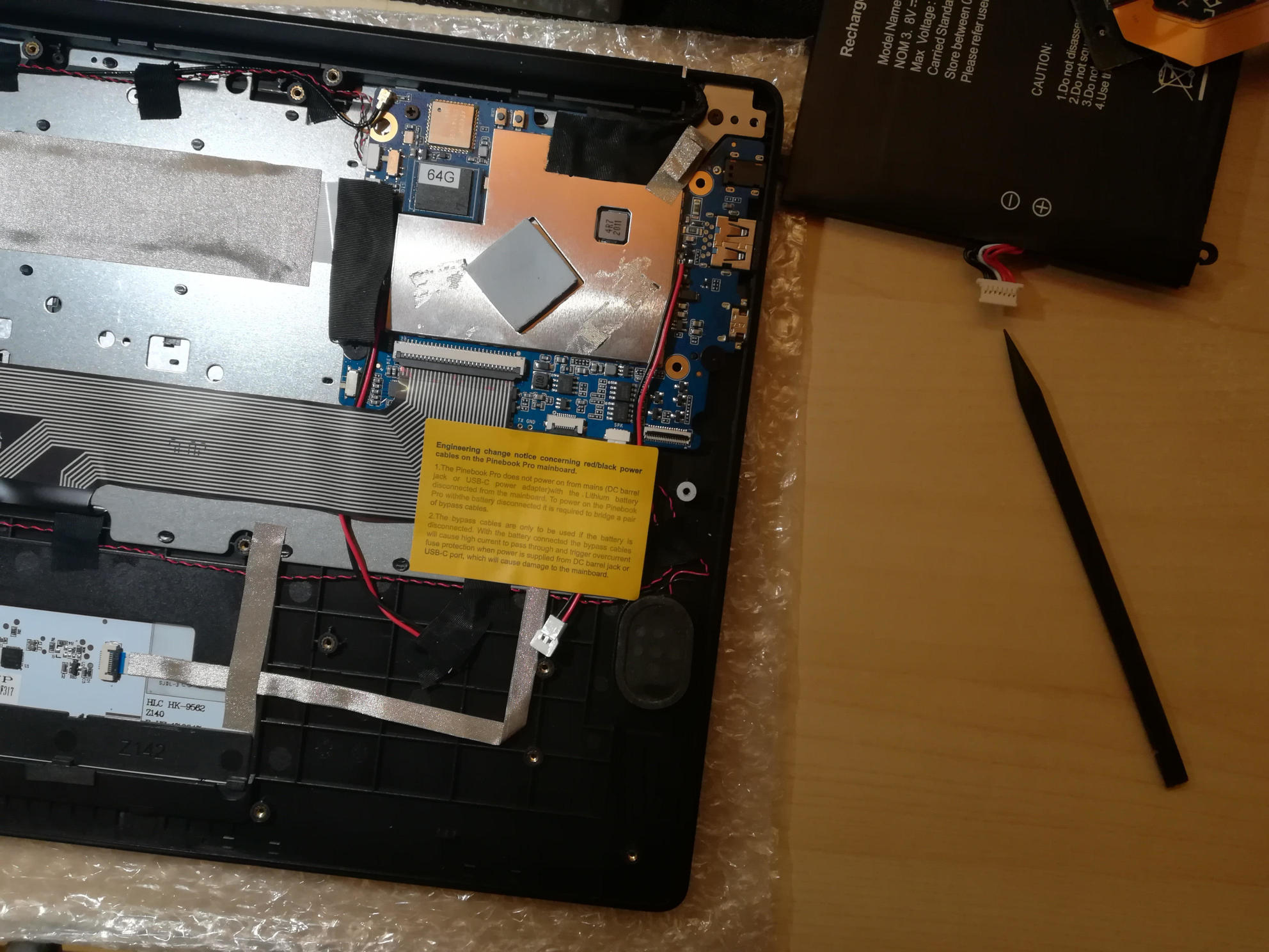
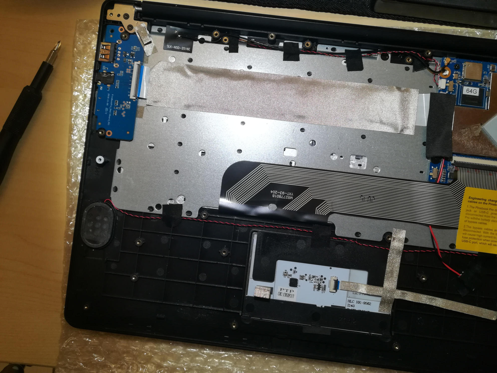
Step 4: Unplug the ribbon cables.
There are several ribbon cables. To remove, flip up the tab and gentle pull the ribbon out.
- One cable runs from the mainboard to the daughterboard underneath the battery. Detach from both ends. With the battery removed, detach from keyboard shell, and set aside for the new keyboard shell.
- One cable runs between the touchpad and the mainboard. Detach from both ends, and also set aside.
- One cable runs between the keyboard and the mainboard. This one remains attached to the keyboard and only needs to be detached from the mainboard.
- One cable from the LCD attaches near the lid hinge. It should be just unplugged.
Step 5: Detach microphone, speakers, and antenna.
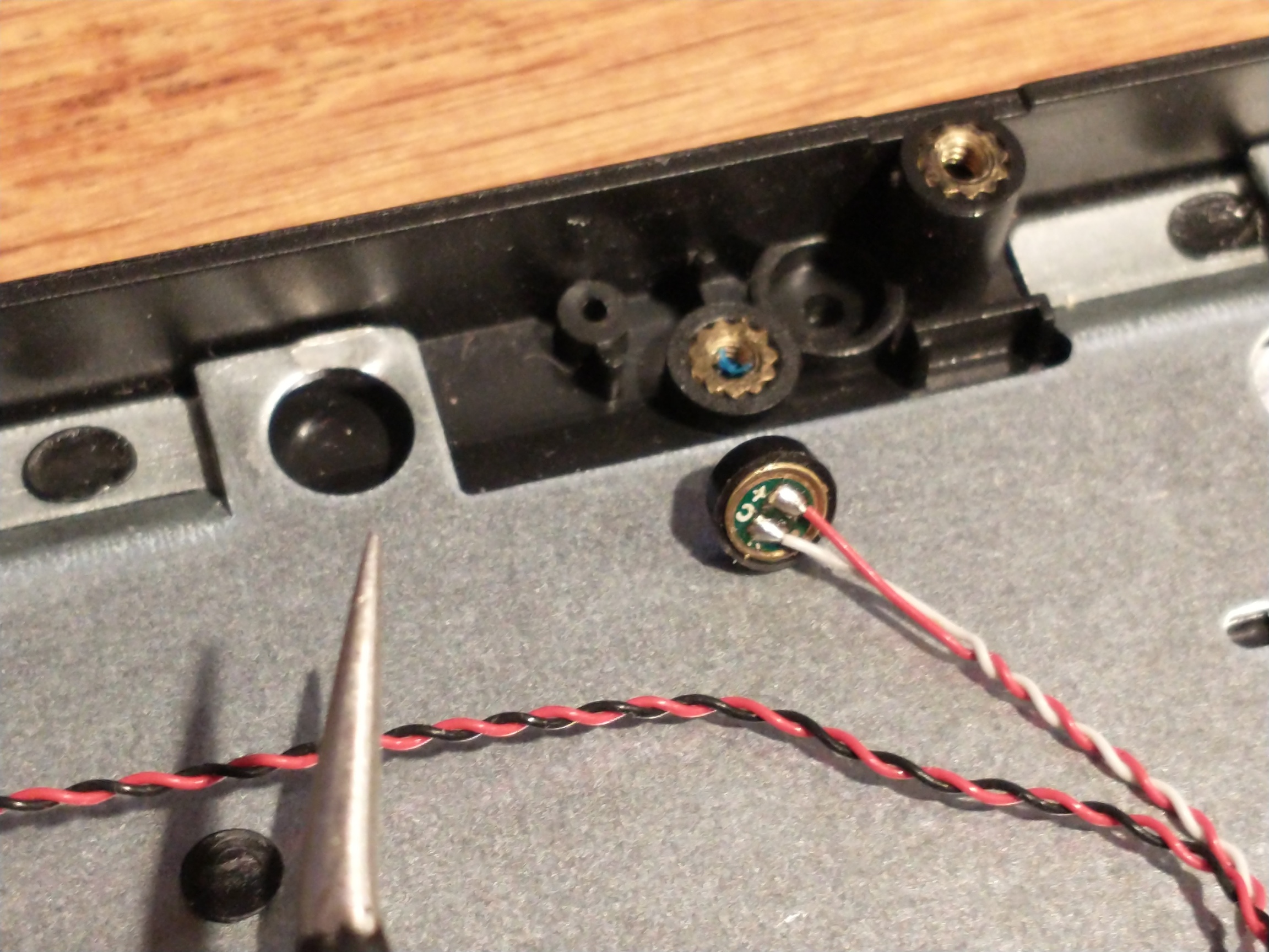
One of the Pinebook Pro microphones after removal
The speakers, microphone, and antenna don’t have to be detached from the mainboard, but they need to be detached from the keyboard shell. The microphones are held in place by tape, and the speakers have sticky sides. The speakers are found obviously, but the microphones (two of) can be found between the battery and the hinge area. Each microphone can be carefully pulled/wedged out of its position by a small screwdriver or pick. The antenna, similar to the microphones, is found near the hinge area and to the top left of the battery.
Step 6: Remove mainboard and daughterboard.
At this point, the mainboard and daughterboards should be removed. When unscrewed (see Step 2) they should pull out fairly easily. Put them aside (including microphones and speakers if left attached.)
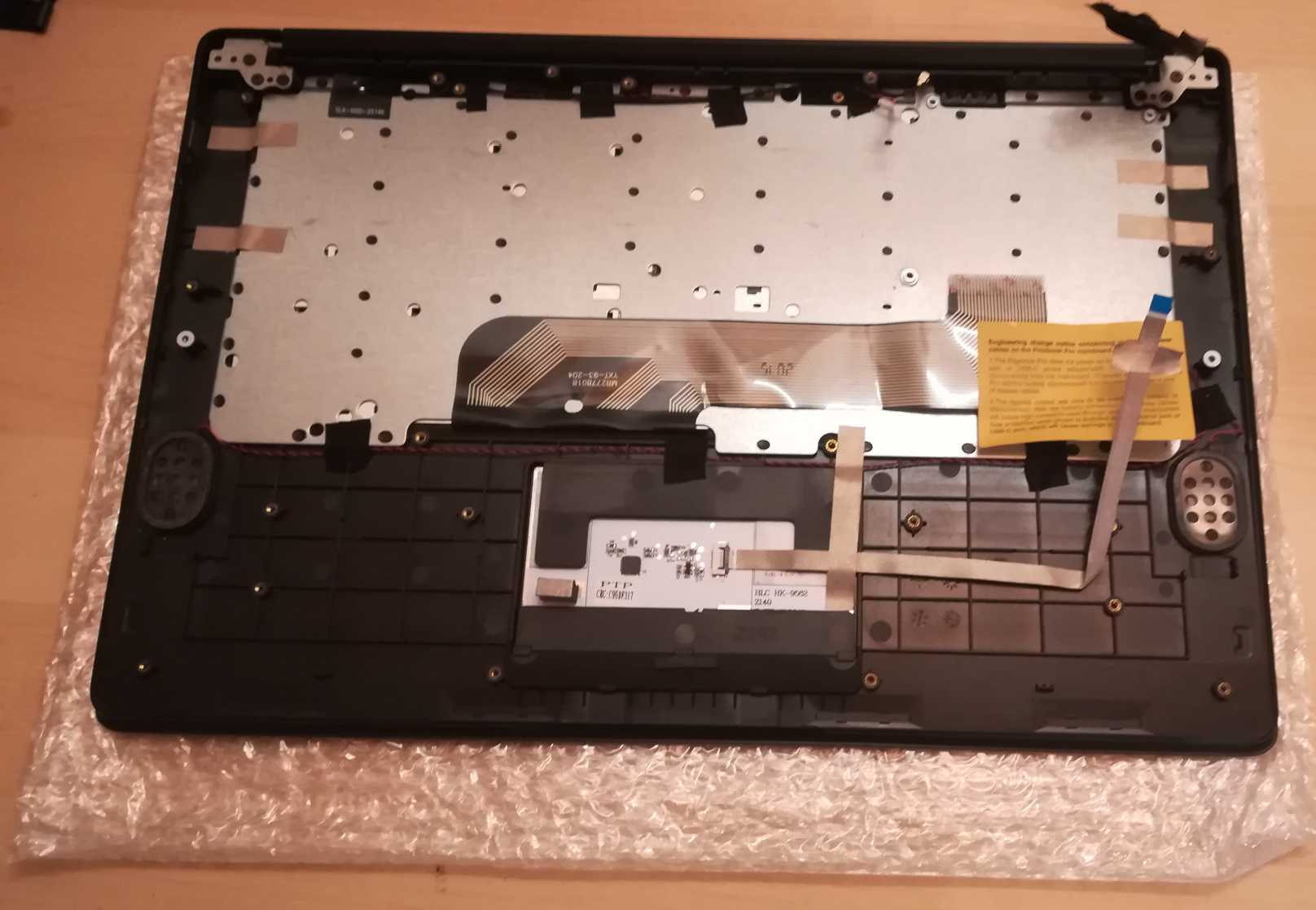
Step 7: Detach the LCD panel.
Step 2 didn’t tell you, there are 6 more screws to remove here, 3 for each of the hinges. I recommend a PH1 bit for these screws. Unscrew these and the LCD panel will be able to be removed. You may have to jiggle or move the hinges for this. When detached, be sure to place the LCD panel such that the display is protected.
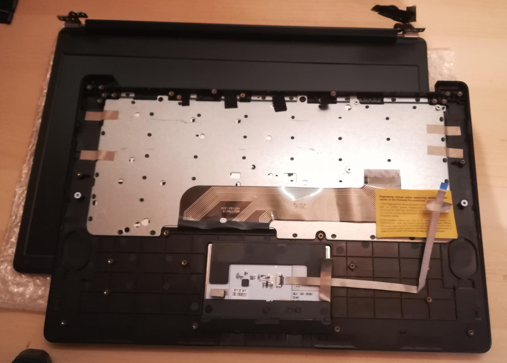
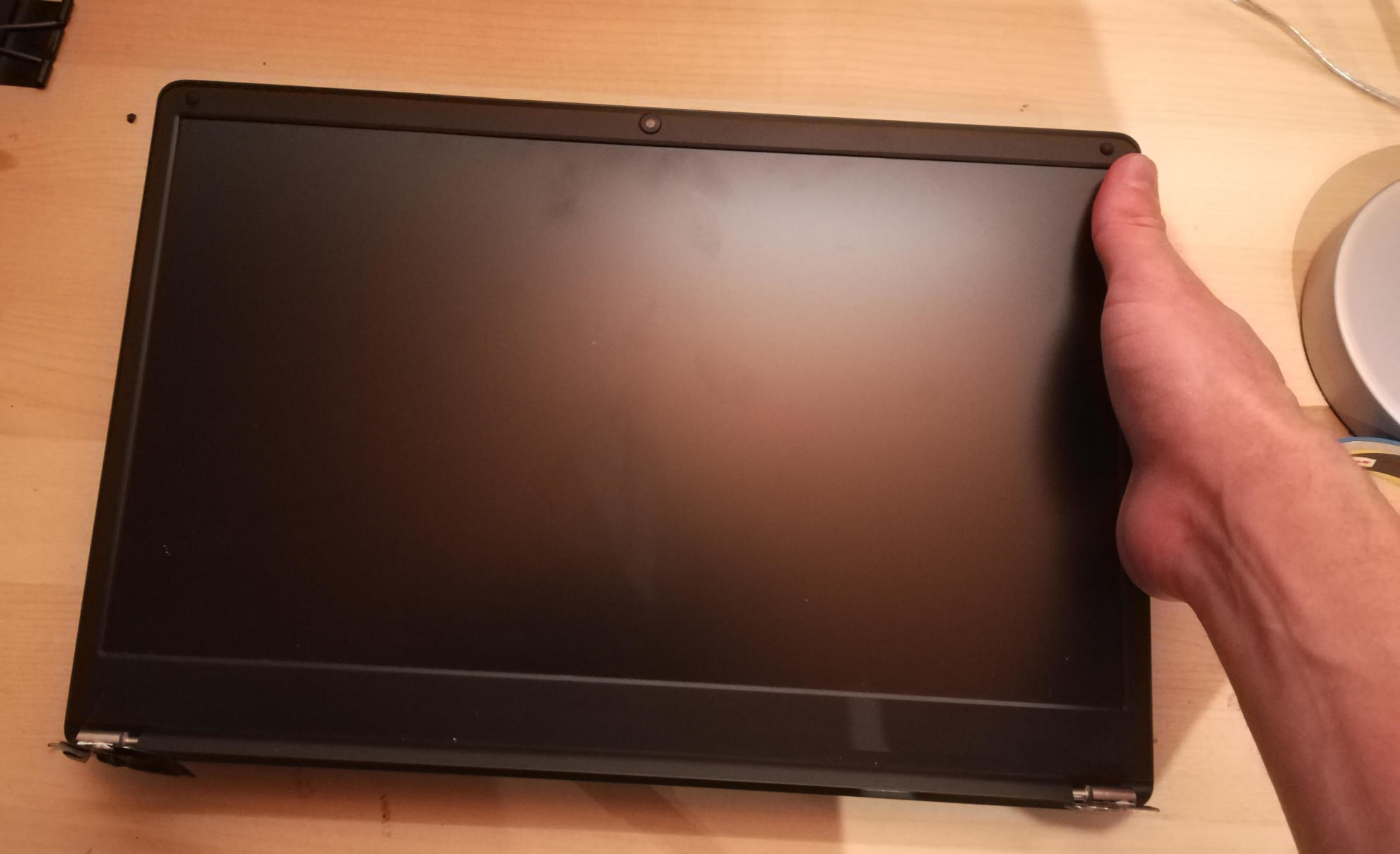
Step 8: Try not to break your touchpad
NOTE This section really feels like you’re going to break something.
The touchpad is glued to the keyboard shell and it’s glued well. There are two places it is glued to. If you can, only the middle must be force-detached. You will think you’re going to break it. Gently apply increasing force until the glue begins to detach (you will hear a crackle as it comes off), and continue very slowly until the whole thing is detached. This may take minutes due to that feeling you’re going to break it.
I found it helpful to lift the top left plastic bit on the keyboard to unstick that portion of the touchpad, then push on the top left portion of the touchpad to unstick the rest of the touchpad.
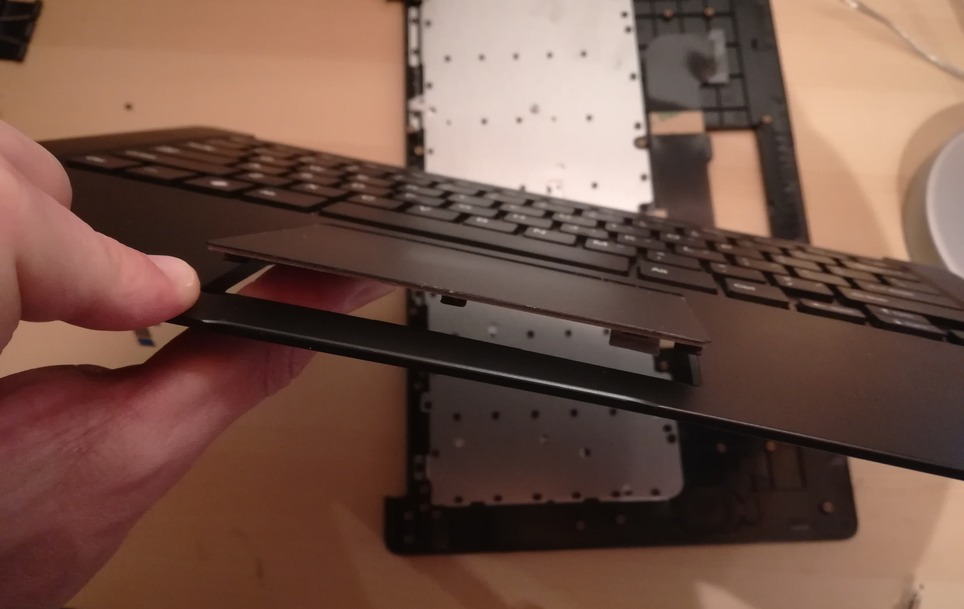
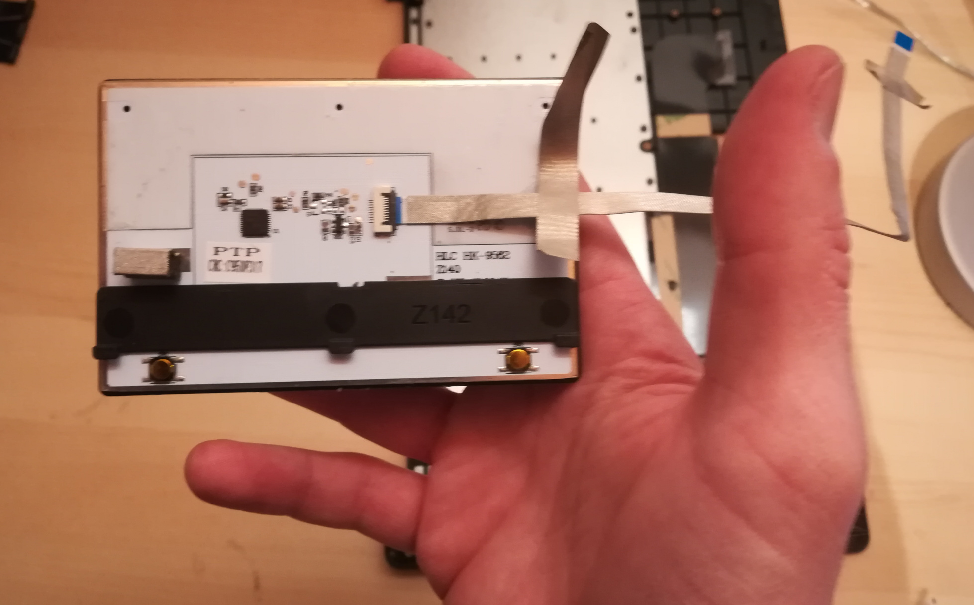
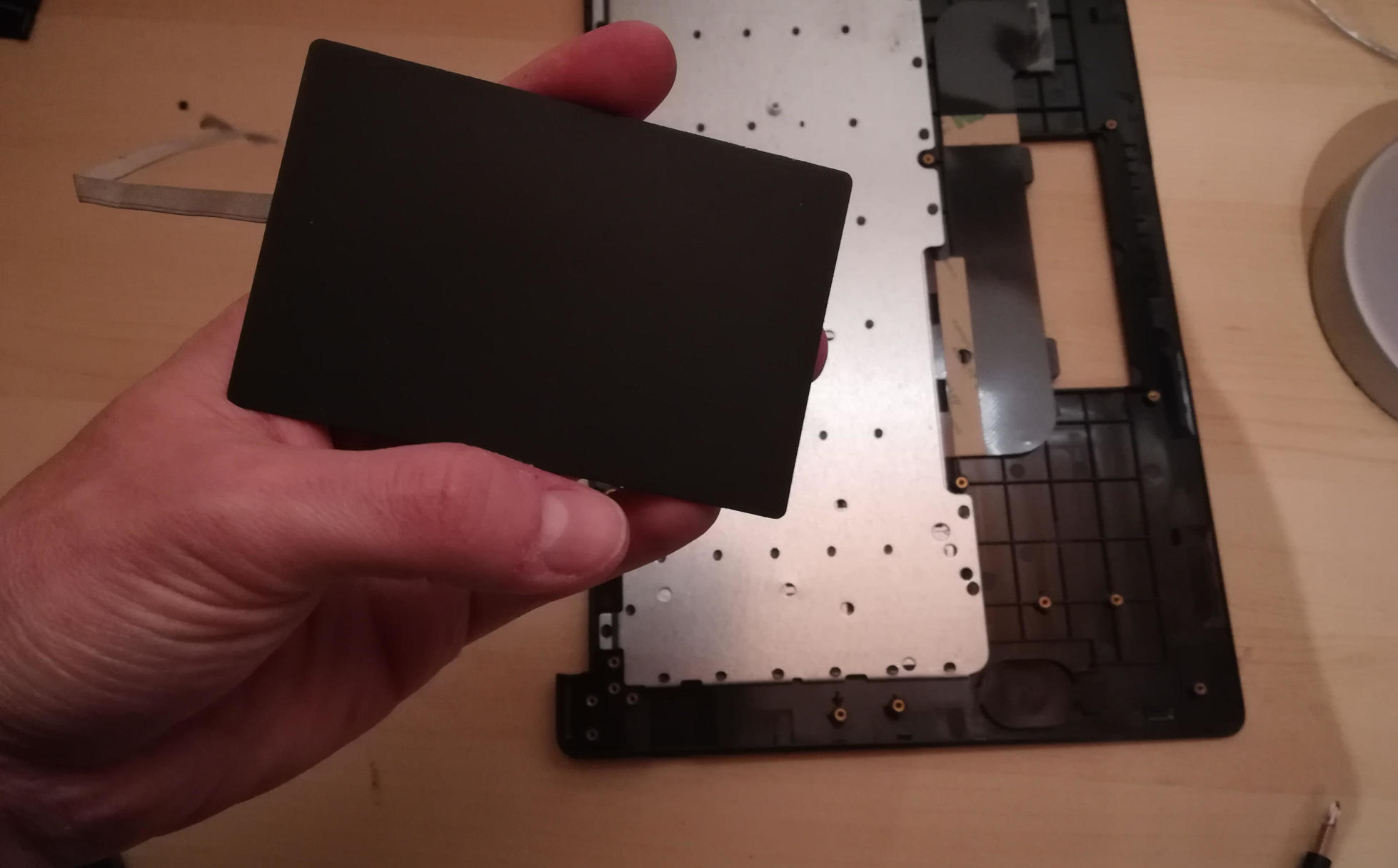
Step 9: Over the hill, touchpad goes into new shell.
In the new keyboard shell put the touchpad back where it was, hopefully the glue will remain sufficiently attached. If there is a glue issue, this guide unfortunately has no advice currently.
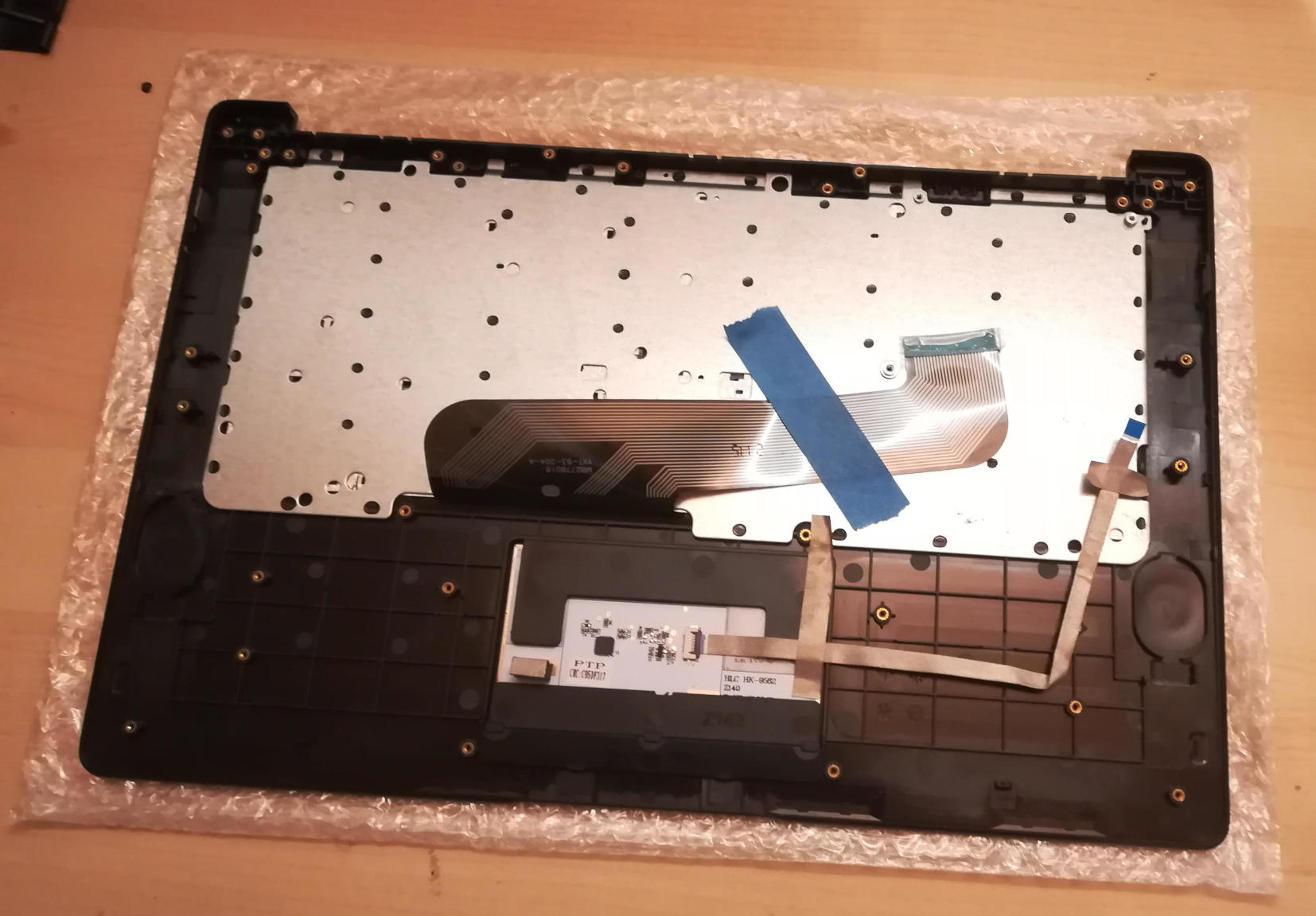
Step 10: Reattach the LCD panel.
The LCD panel should slot back into the keyboard frame, the same way it came out. If the hinges were moved, they should be very gently closed such that the LCD panel and keyboard closed like normal for the remaining steps.
Step 11: Tape it out.
Move any tape from the old keyboard shell to the new one. These items protect the mainboard and daughterboard, and keep various wires in their right place. Some are grey and some are black. For tape that holds the speakers, microphones, or their cables in place, do not reattach yet.
Step 12: Board install.
Install the mainboard, the daughterboard, and their connecting ribbon cable. Be sure to put the boards in place, 2 large flat screws for the daughterboard, 3 large flat screws and one small screw for the mainboard, before attempting to place the ribbon.
Step 13: Microphone, speaker, and antenna install.
Reattach the microphones, antenna, and speakers to their respective areas, making sure that both are properly oriented - the speaker “out” faces up, and the microphone cables as connected must face up (these are opposite directions.)
Step 14: Reattach other ribbon cables.
The LCD panel, keyboard and touchpad ribbon cables should be reattached. Make sure the flap is open, insert the ribbon into the slot (a portion of the cable will disappear), and push the flap down. The cable should not be easy to pull out.
Step 15: Reattach the battery, and final re-tape.
The battery should be installed with the 4 screws holding it in place, and the connector attached to the mainboard. Be sure to keep the two other cables remain unconnected. Ensure all wires and other tapes are held in place.
Step 16: Reattach the back panel.
Put the back panel back on, and reattach the 10 screws.
Step 17: If you changed from ISO to ANSI or from ANSI to ISO, you’ll need to update your firmware now. See the links in Step 0 above.
Assembly
Please help to review and edit this page or section. Information are subject to change.
The Pinebook Pro keyboard comes as a pre-assembled unit built into the main shell of the device, a damaged shell had the keyboard removed from it to be studied. Note that removing the keyboard from the shell is technically irreversible since it’s held in with melted plastic rivets. If these ever happen to break then you could likely hold the keyboard in with adhesives or drill small holes and use screws instead.
The keyboard is sandwiched between a thick (likely 0.7mm) steel plate and the plastic shell, this steel plate serves as a mounting point for some of the components inside the laptop as well as adding a significant amount of structural rigidity to the device. The actual keyboard is made of a very thin metal backplate, a clear flexible plastic PCB, and a black flexible plastic layer that appears to be removable but more research will need to be done.
The key mechanism is a relatively modern style of scissor switch, the upside to this mechanism is that the keys have a very nice feel to them and don’t fall apart easily, the downside is that if the plastic scissor mechanism gets damaged the whole key assembly will start to fall off due to slipping out from under the metal arms in the keyboard backplate. The only known fix is to replace the key assembly, or more likely the entire keyboard mechanism, more research should be done into this.
Older style scissor switches allowed you to just pull the keycap straight off the mechanism and snap it back into place by pressing down on it. Do not do this for newer mechanisms like the Pinebook Pro keyboard, all that will do is damage the mechanism.
Removing Keys
Keys can be relatively safely removed (however the mechanism can easily be damaged by someone who doesn’t know what they’re doing) when the keyboard assembly has been removed from the shell, however with the shell in place it blocks movement of the keys that is required to unhook the mechanism from the metal backplate.
To remove a key, first push it all the way in, slide it upwards slightly, and lift the top half of the key, this should dislodge the upper half of the scissor mechanism, this step can be tricky, the keys were designed to be assembled once and never removed again.
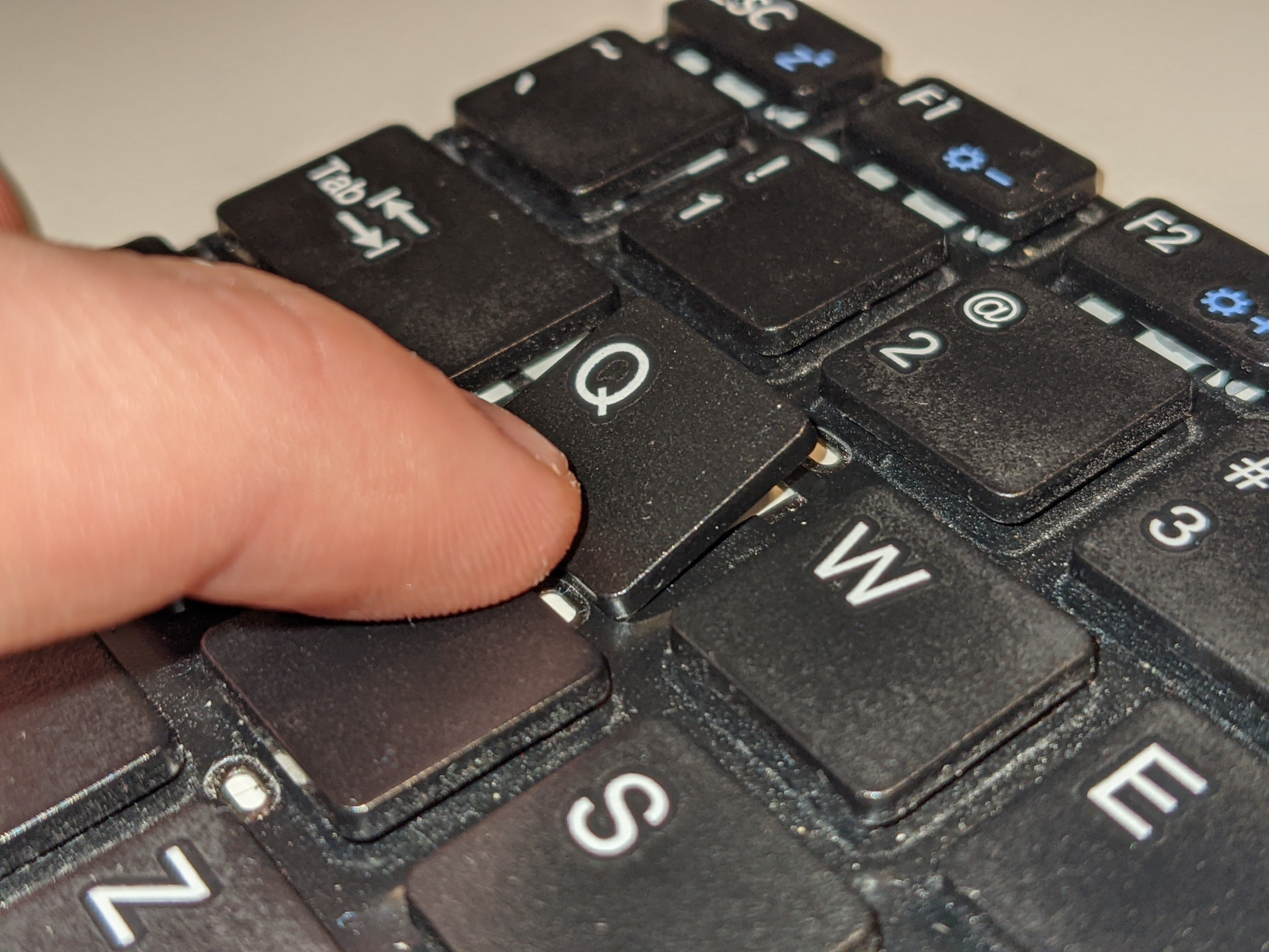
Next you can just slide the key down slightly, this will dislodge the lower half of the scissor mechanism and the key should come completely off the keyboard.
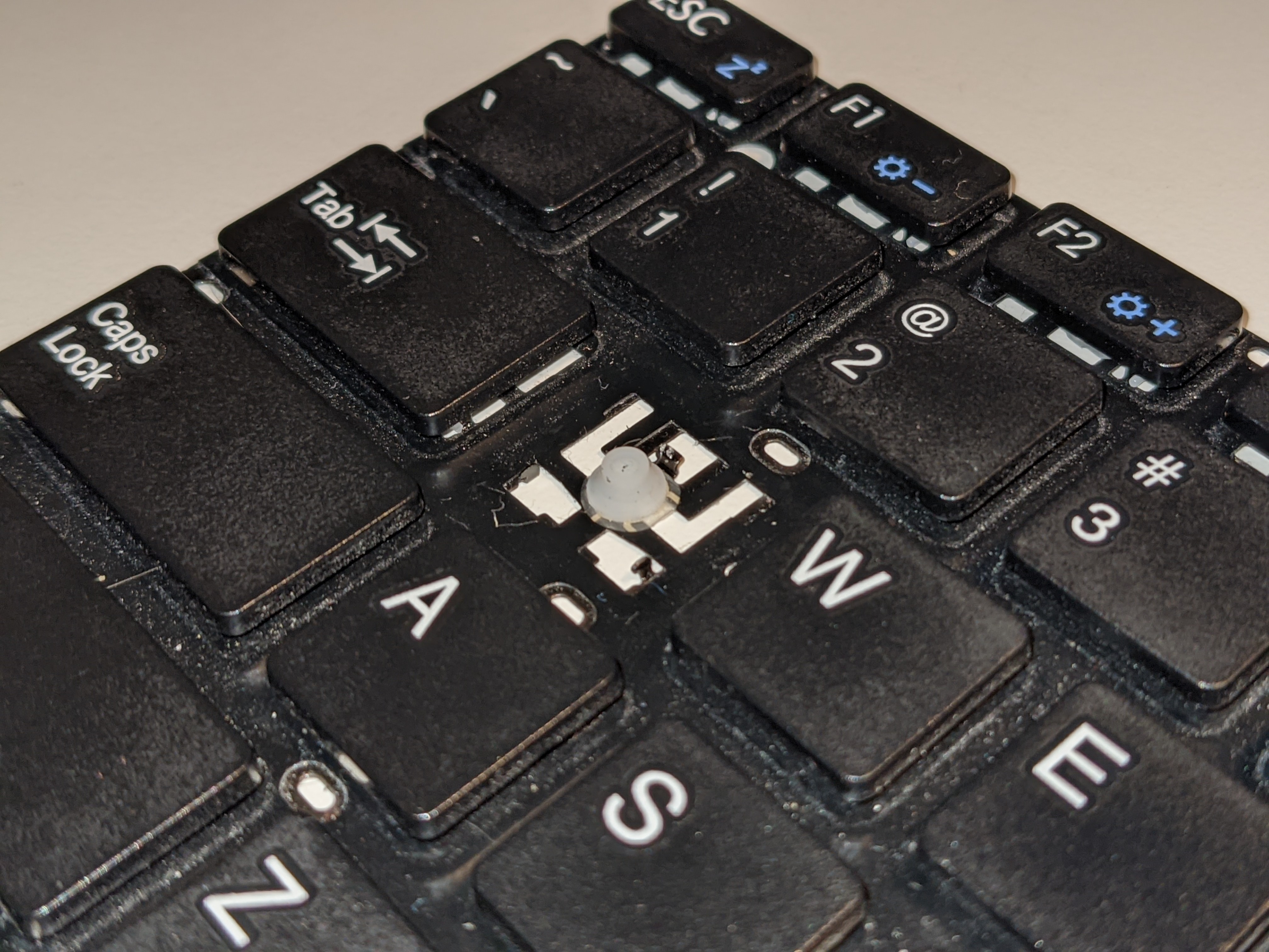
Re-attaching a key can be quite fiddly since the mechanism stays attached to the key rather than the keyboard like older scissor designs.
The assembly process is the same as disassembly, just reversed, but you have to be careful with horizontal alignment, otherwise the lower half of the mechanism won’t lodge in place.
Note that if a key mechanism is damaged, pressing in the upper corners of the key will cause it to dislodge and fall off the keyboard.
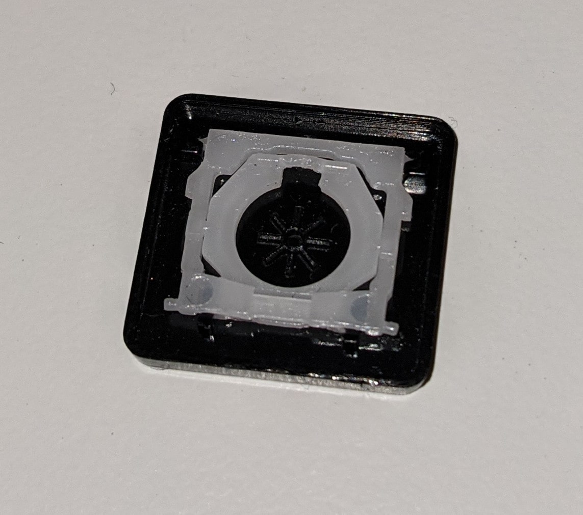
Damaged keys might look like this, note that the pin on the lower right side of the mechanism is slightly deformed and the latch on the upper half of the mechanism is bowed out slightly and cracked. This is enough damage to cause the key to pop out when pressed in the upper corners.
Guides
Caring
Bypass Cables
The mainboard features two bypass cables that are to be used only with the battery disconnected. The two bypass cables are disconnected by default. The female (10) male (6) ends of the bypass cables can be connected to provide power to the mainboard if you need to run your Pinebook Pro with no battery. Please refer to this engineering notice for more details.
Connecting the bypass cables together effectively connects the charger input where the battery output is, which also bypasses the charging circuit inside the Pinebook Pro. Thus, with the bypass cables connected together, the charger powers the Pinebook Pro directly, just like the battery does it when the laptop is running on battery power. This also means that no input current limiting is any longer in place, making it possible to draw more than 3 A from the charger, and to trigger its overcurrent protection, which may cause operating system instability and crashes.
Despite the bypass cables having two conductors, they are used as a single conductor. Having both wires soldered together on either side of the bypass cables is normal, and such load-sharing design allows use of a compact connector on the bypass cables.
When removing the large RF shield found on the mainboard, for example when shorting the pins on the SPI chip, make absolutely sure to align it correctly while putting it back. Failing to do so can result in shorting the battery to the ground, due to the close proximity of the solder pads for the bypass cables, which would prevent the normal operation and effectively cause a fire hazard. It is highly recommended to disconnect the battery before removing the RF shield, and before putting it back.
Guides
These are self-service instruction guides for the disassembly of the 14-inch Pinebook, but they still almost directly apply to the Pinebook Pro:
Assembling it back requires the described steps to be performed in the reverse order.
Disassembly and Reassembly
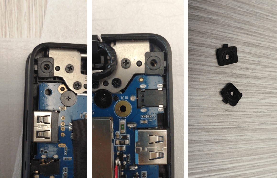
Pinebook Screw stand-offs correct placement and location
Hinge_area_of_the_Pinebook_Pro_lid_with the cover removed Close-up of a Pinebook Pro lid hinge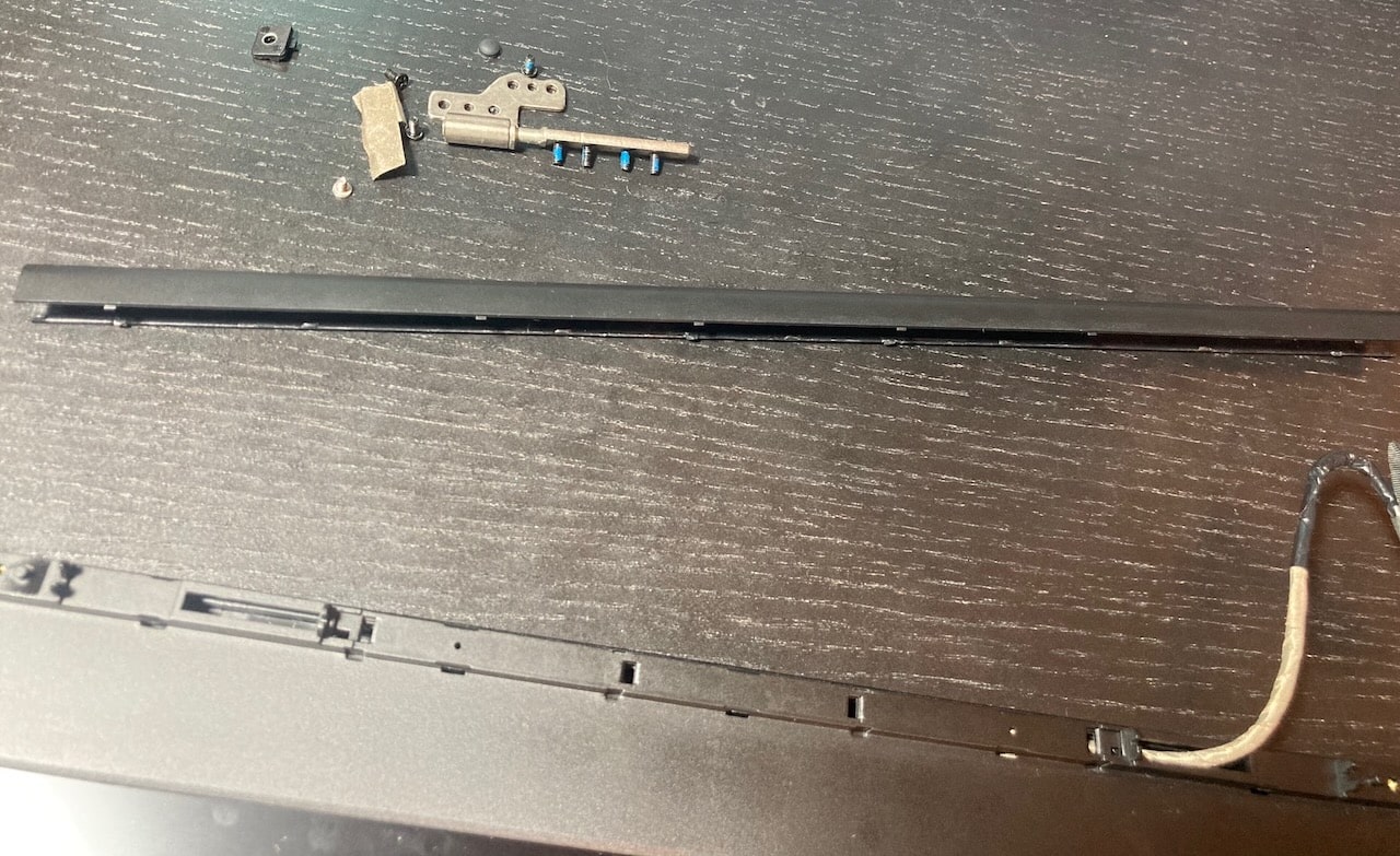
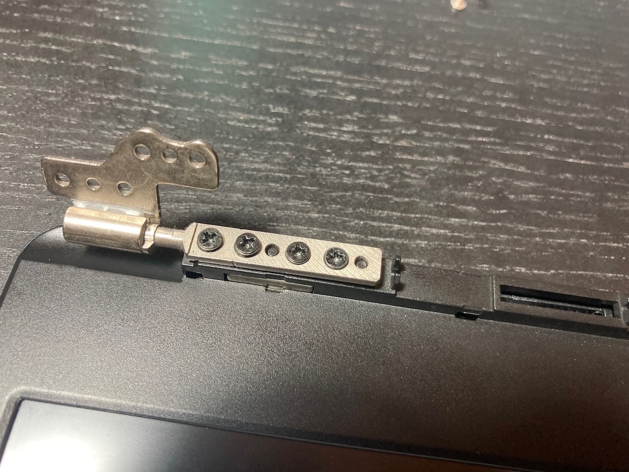
There are a few mandatory precautions to be taken:
- Do not open the laptop by lifting the lid while the Pinebook Pro bottom cover is removed - this can cause structural damage to the hinges and/or other plastic components of the chassis such as the IO port cut-outs.
- When removing the back cover plate, do not, under any circumstances, slide your fingertips between the metal shell and the plastic frame! The back cover plate edges are sharp, and when combined with the pressure and movement generated from, specifically, attempting to slide the tips of your fingers along the bottom edge of the plate along the lid-hinge, they will slice open the tips of your fingers like a knife.
- When removing the back cover plate, use care to avoid damaging the speakers. They can be stuck to the back cover with double-sided tape, and the thin wires are very delicate. Newer Pinebook Pro laptops (as of the May 2021 batch, and perhaps earlier) seem to lack the double-sided tape to the rear cover, instead opting for tape or glue that makes them stick to the front cover. Nevertheless, be gentle when removing the back cover.
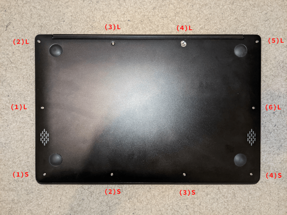
Pinebook Pro external screws (this particular unit has suffered damage on screw (4)L)
When disassembling the laptop make sure that it is powered off and folded closed. To remove the bottom cover of the Pinebook Pro, first remove the ten (10) Phillips head screws that hold the bottom section of the laptop in place. There are four (4) short screws along the front edge, and six (6) long screws along the 3 remaining sides. Remove the cover from the back where the hinges are situated by lifting it up and away from the rest of the chassis. The aluminum case is held on only by screws. There are no plastic snaps, and the shell should pull away without any effort. If you experience any resistance at all stop and ensure all ten (10) screws are accounted for.
During reassembly, make sure that the back-screw standoffs are in place and seated correctly. Before replacing the aluminum back-plate, ensure that the speakers are properly seated by pressing gently on the hard plastic edge of the speaker module. Slide the bottom section into place so it meets the front lip of the keyboard section. Secure the front section (where the touchpad is located) in place using the short screws in the front left and right corners. Then proceed to pop in the bottom panel into place. Secure the bottom section (where hinges are located) by screwing in the left and right corners. Then screw in the remaining screws and run your finger though the rim on the chassis to make sure its fitted correctly. Note that the front uses the remaining 4 short screws.
The screws are small and should only be finger tight. Too much force will strip the threads. If after installing screws the back cover plate has not seated properly on one side (which may be caused by the aforementioned misseating of the speakers), open the display and hold the base on either side of the keyboard and gently flex the base with both hands in opposing directions. Once the side pops further in, then recheck the screws on that side. If it does not pop back in, re-open the machine and check for misseated components.
A basic 3D model to print replacement standoffs for the back cover screws is available on Thingiverse, until the official drawings or 3D models are made available.
Many units come with the hinges too stiff from the factory. You can tell if it affects your device by carefully observing if operating the lid on a fully assembled notebook flexes the case. This repeated flexing can lead to plastic and metal fatigue and eventually broken parts. Consider carefully using a flat screwdriver or similar object to unbend the hinges a bit by wedging it into the slot (requires the display part to be fully detached from the main body).
Display disassembly
It is not recommended to adjust the position of the lid when the bottom cover is removed, because the bottom cover provides structural strength, so the lid should be open fully as the first step, before starting any disassembly of the laptop. After opening the lid, remove the bottom cover by following the instruction found in the section above. Alternatively, you can keep the lid closed and remove the screws that hold the hinges to the main laptop body, as described in Pinebook Service Step by Step Guides.
Parts of the hinge mechanism, as well as the screws that hold the hinges to the lid, are hidden behind an elongated plastic U-shaped cover that snaps in place using latches. Use a dedicated plastic prying tool or a guitar pick to gently pry the cover and remove it, starting from the outer edge. Once you pry the cover to a certain extent, it should be possible to remove it fully using only your hands. The U-shaped cover is rather sturdy, but still be careful not to break or bend it.
There are two small screws hidden underneath the two small rubber nubs on the upper part of the screen bezel, so first gently remove the nubs and then remove the screws. The screen bezel is held in place with a combination of latches and some adhesive tape, which is there to prevent dust ingress. The adhesive isn’t very strong, and the bezel is capable of flexing back into shape after being twisted to a certain extent. There is more adhesive on the bottom part of the screen bezel, so be more careful while prying that section apart. Use the same prying tool that you used for the U-shaped cover, and work it around the outer edges of the screen bezel.
Skinning and case customization
Template files for creating custom skins. Each includes template layers for art placement, and CUT lines:
Using the optional NVMe adapter
The optional NVMe adapter allows the use of M.2 SSDs that support the NVMe standard (SATA is not supported). The adapter supports M and M+B keyed devices, in both 2242 and 2280 physical sizes, which are the most commonly available. In addition, 2230 and 2260 sizes are also supported, though NVMe devices that use those sizes are rare.
Make sure to read the notes in Accessory compatibility before selecting an M.2 SSD for your Pinebook Pro, because there are certain limitations. Once you have fitted and tested your NVMe drive, please consider adding a note to that page
Please see a separate section that describes reported issues with the NVMe drives in Pinebook Pro.
Installing the adapter
The V2.1-2019-0809 SSD adapter that shipped with the initial Pinebook Pro batches had significant issues. A repair kit will be shipped to address those issues. (If necessary, it can be modified to work. There is an unofficial tutorial on the forums describing these modifications.)
The updated SSD adapter, labeled V2-2019-1107, takes into account the prior problems with touchpad interference. New orders as of Feb. 22nd, 2020 will be the updated adapter.
This is the link to the Pinebook Pro accessories in the store: https://pine64.com/?v=0446c16e2e66
Actual installation instructions are a work in progress. Unofficial instructions for installing V2-2019-1107 can be found here.
Post NVMe install power limiting
Some NVMe SSDs allow reducing the maximum amount of power. Doing so may reduce the speed, but it may be needed in the Pinebook Pro to both improve reliability on battery: Some NVME may be stable with default settings when running on AC power but cause frequent kernel panics (system freeze with power LED blinking red/green) when running on battery. Reducing NVME power drain solves this in some cases. And reducing power used gives better battery life. Here are the commands to obtain and change the power settings. The package ’nvme-cli’ is required to run these commands. The example shows how to find the available power states, and then sets it to the lowest, non-standby setting, (which is 3.8 watts for the device shown):
$ sudo nvme id-ctrl /dev/nvme0
NVME Identify Controller:
...
ps    0 : mp:9.00W operational enlat:0 exlat:0 rrt:0 rrl:0
         rwt:0 rwl:0 idle_power:- active_power:-
ps    1 : mp:4.60W operational enlat:0 exlat:0 rrt:1 rrl:1
         rwt:1 rwl:1 idle_power:- active_power:-
ps    2 : mp:3.80W operational enlat:0 exlat:0 rrt:2 rrl:2
         rwt:2 rwl:2 idle_power:- active_power:-
ps    3 : mp:0.0450W non-operational enlat:2000 exlat:2000 rrt:3 rrl:3
         rwt:3 rwl:3 idle_power:- active_power:-
ps    4 : mp:0.0040W non-operational enlat:6000 exlat:8000 rrt:4 rrl:4
         rwt:4 rwl:4 idle_power:- active_power:-
$ sudo nvme get-feature /dev/nvme0 -f 2
get-feature:0x2 (Power Management), Current value:00000000
$ sudo nvme set-feature /dev/nvme0 -f 2 -v 2 -s
set-feature:02 (Power Management), value:0x000002
Some NVMe SSDs don’t appear to allow saving the setting with “-s” option. In those cases, leave off the “-s” and use a startup script to set the non-default power state at boot. If you want to test performance without saving the new power setting semi-permanently, then leave off the “-s” option.
On systemd based distributions like Manjaro, a non-default power state for an NVME can be set using a systemd service. This is useful in cases where the NVME drive does not save the power state and/or uses APST. An example systemd service, nvme-throttle.service, is shown below:
[Unit]
Description=Throttles NVME to lesss power hungry mode
After=suspend.target hibernate.target hybrid-sleep.target suspend-then-hibernate.target

[Service]
Type=oneshot
ExecStart=/usr/bin/nvme set-feature /dev/nvme0 -f 2 -v 1

[Install]
WantedBy=multi-user.target suspend.target hibernate.target hybrid-sleep.target suspend-then-hibernate.target
Here the value after “-v” is the maximum power state that you want your SSD to use. This will be executed at system startup, and every time your system exits any suspend mode that might reset the SSD to default values.
This file needs to be placed in the /etc/systemd/system directory. Afterwards, to activate the service, run:
systemctl daemon-reload
systemctl enable --now nvme-throttle.service
There is another power saving feature for NVMes, APST, (Autonomous Power State Transitions). This performs the power saving & transitions based on usage. To check if you have a NVMe SSD with this feature:
$ sudo nvme get-feature -f 0x0c -H /dev/nvme0
Information for this feature, (on a Pinebook Pro), is a work in progress. It is enabled by default in latest Manjaro kernels and reported to work. On some NVME SSDs (WD), APST is compatible with limiting NVMe maximum power: APST will work and not exceed maximum power state defined using previous method.
Using as data drive
As long as the kernel in use has both the PCIe and NVMe drivers, you should be able to use a NVMe drive as a data drive. It can automatically mount when booting from either the eMMC or an SD card. This applies to Linux, FreeBSD, and Chromium, using the normal partitioning and file system creation tools. Android requires testing.
Using as OS root drive
The SoC does not include the NVMe boot code, so the NVMe is not in the SoC’s boot order. However, using the U-Boot update script from the mrfixit2001 Debian or Arglebargle’s modified script, and the modified u-boot images provided by forum user pcm720, you can now add support to boot from an NVMe drive. Binary images are useable with SD, eMMC, and SPI flash. For OS images using the mainline kernel, there are a few variants of U-Boot available that also support NVMe as the OS drive. Though these may require writing the U-Boot to the SPI flash for proper use of the NVMe as the OS drive.
The current boot order, per last testing, for this modified U-Boot is:
- MicroSD
- eMMC
- NVMe
For more information, please refer to the forum post.
It is also possible to initially boot off an eMMC or SD card, then transfer to a root file system on the NVMe. Currently, it is necessary to have the U-Boot code on an eMMC or SD card. (A forum member posted here about using a modified version of U-Boot with NVMe drivers, that uses /boot and / off the NVMe drive. So this may change in the future.)
Please see Bootable Storage.
Using the SPI flash device
See SPI for details.
The Pinebook Pro comes with a 128 Mbit, (16MByte), flash device suitable for initial boot target, to store the bootloader. The SoC used on the Pinebook Pro boots from this SPI flash device first, before eMMC or SD card. At present, April 19, 2020, the Pinebook Pros ship without anything programmed in the SPI flash device. So the SoC moves on to the next potential boot device, the eMMC. ARM/ARM64 computers do not have a standardized BIOS, yet.
Here is some information on using the SPI flash device:
- You need the kernel built with SPI flash device support, which will supply a device similar to: /dev/mtd0
- The Linux package below, will need to be available: mtd-utils
- You can then use this program from the package to write the SPI device:
flashcp <filename> /dev/mtd0
Even if you need to recover from a defective bootloader written to the SPI flash, you can simply short pin 6 of the SPI flash to GND and boot. This will render the SoC bootrom unable to read from the SPI flash and have it fall back to reading the bootloader from other boot media like the eMMC or Micro SD card.
The procedures described above are a lot less risky than attaching an external SPI flasher and do not require any additional hardware. At present, April 19th, 2020, there is no good bootloader image to flash into the SPI flash device. This is expected to change, as there are people working on issue.
Further information
Case dimensions and data
- Dimensions: 329 mm x 220 mm x 12 mm (W x D x H)
- Weight: 1.26 kg
- Screws on the bottom lid
- Philips-head type screws
- M2 flat-head machine screws
- 4 x short screw (used along the front edge): head diameter - 3.44 mm, thread diameter - 1.97 mm, thread length - 2.1 mm, overall length - 3.05 mm
- 6 x long screw (used elsewhere): head diameter - 3.44 mm, thread diameter - 1.97 mm, thread length - 4.41 mm, overall length - 5.85 mm
- Rubber feet
- 18 mm diameter
- 3 mm height
- Dome shaped
Datasheets
Rockchip RK3399 SoC information:
- Rockchip RK3399 SoC Brief
- Rockchip RK3399 Datasheet v2.1
- Rockchip RK3399 Technical Reference Manual v1.4, part 1
- Rockchip RK3399 Technical Reference Manual v1.3, part 1 and part 2
- Rockchip RK808 Datasheet v0.8
LPDDR4 SDRAM (366-pin BGA):
eMMC information:
- PINE64 eMMC module schematic
- PINE64 USB adapter for eMMC module V2 schematic
- PINE64 USB adapter for eMMC module PCB in JPEG
- 64GB/128GB SanDisk eMMC Datasheet
SPI NOR Flash information:
Wireless and Bluetooth information:
Audio codec:
LCD panel:
USB-related information:
- Internal USB 2.0 hub: GL850G USB Hub Datasheet
- USB Type-C Controller: ON Semiconductor FUSB302 Datasheet
Touchpad information:
Keyboard information:
- Sinowealth SH68F83 Datasheet
- US ANSI: XK-HS002 MB27716023
Full HD camera sensor:
Battery-related information:
- Battery charging IC: Texas Instruments BQ24171 Datasheet
- Battery monitoring IC: Cellwise CW2015 Datasheet
- 10000 mAH Lithium Battery Specification
- Later batches 9600 mAh / 36.48 Wh model WYC40110175P Lithium Battery Specification
Power path device:
NVMe adapter:
Schematics and certifications
Pinebook Pro Main Board Schematic And Silkscreen:
- Pinebook Pro Main Board ver 2.1a Schematic 20220419
- Pinebook Pro Main Board ver 2.1 Schematic 20190905
- Pinebook Pro ver 2.1 Top Layer Silkscreen
- Pinebook Pro ver 2.1 Bottom Layer Silkscreen
Pinebook Pro Daughter Board Schematic:
Optional Pinebook Pro NVMe Adapter Schematic:
Serial Console Earphone Jack Pinout:
Pinebook Pro Case:
Pinebook Pro Certifications:
Specifications
Based on Rockchip RK3399
CPU Architecture
big.LITTLE architecture: Dual Cortex-A72 + Quad Cortex-A53, 64-bit CPU
- Full implementation of the ARM architecture v8-A instruction set (both AArch64 and AArch32)
- ARM Neon Advanced SIMD (single instruction, multiple data) support for accelerated media and signal processing computation
- ARMv8 Cryptography Extensions
- VFPv4 floating point unit supporting single and double-precision operations
- Hardware virtualization support
- TrustZone technology support
- Full CoreSight debug solution
- One isolated voltage domain to support DVFS
Cortex-A72 (big cluster):
- Dual-core Cortex-A72 up to 2.0GHz CPU
- Superscalar, variable-length, out-of-order pipeline
- L1 cache 48KB Icache and 32KB Dcache for each A72
- L2 cache 1024KB for big cluster
Cortex-A53 (little cluster):
- Quad-core Cortex-A53 up to 1.5GHz CPU
- In-order pipeline with symmetric dual-issue of most instructions
- L1 cache 32KB Icache and 32KB Dcache for each A53
- L2 cache 512KB for little cluster
Cortex-M0 (control processors):
- Cortex-M0 CPU
- Two Cortex-M0 cooperate with the central processors
- Architecture: Armv6-M
- Thumb/Thumb2 instruction set
- 32 bit only
GPU Architecture
- ARM Mali-T860MP4 Quad-core GPU
- The highest performance GPUs built on Arm Mali’s famous Midgard architecture, the Mali-T860 GPU is designed for complex graphics use cases and provide stunning visuals for UHD content.
- Frequency 650MHz
- Throughput 1300 Mtri/s, 10.4 Gpix/s
Graphic interface standards:
- OpenGL® ES 1.1, 1.2, 2.0, 3.0, 3.1, 3.2 (Panfrost has initial support of 3.0 beginning 2020/02/27)
- Vulkan 1.0, using the Mali binary blob (Panfrost does not support Vulkan as of 2020/06/24)
- OpenCL™ 1.1, 1.2
- DirectX® 11 FL11_1
- RenderScript™
System Memory
RAM Memory:
- LPDDR4
- 800 MHz (limited by RK3399)
- Dual memory channels on the CPU, each 32 bits wide
- Quad memory channels on the RAM chip, each 16 bits wide, 2 bonded together for each CPU channel
- 4 GB as a single 366 pin mobile RAM chip
Storage Memory:
- 64GB eMMC module, can be upgraded to an 128GB eMMC module. (The initial PINE64 community build version shipped with a 128GB eMMC.)
- eMMC version 5.1, HS400, 8 bit on RK3399 side
- Bootable
SPI flash:
- SPI
- 128 Mbit / 16MByte
- 1 bit interface
- Bootable, (first boot device, ahead of eMMC & SD card)
- U-Boot images can be made to work, but as of 2020/06/24 there is no standardized image available.
Video out
- USB-C Alt mode DP
- Up to 3840x2160 p60, dependant on adapter, (2 lanes verses 4 lanes)
Expansion Ports
MicroSD card:
- Bootable
- Supports SD, SDHC and SDXC cards, up to 512GB tested. SDXC standard says 2TB is the maximum.
- Version SD3.0, (MMC 4.5), up to 50 MB/s
- SD card Application Performance Class 1 (A1), (or better), recommended by some users, for better IOPS
USB ports:
- 1 x USB 2.0 Type-A Host Port, bootable
- 1 x USB 3.0 Type-A Host Port, 5 Gbps, is not bootable
- 1 x USB 3.0 Type-C OTG Port, 5 Gbps, (includes laptop charging function), is not bootable
- Note that high power USB devices may not work reliably on a PBP. Or they may draw enough power to drain the battery even when the PBP is plugged into A.C. One alternative is externally powered USB devices.
Headphone jack switchable to UART serial console mux circuit


