Quartz64 (Single Page)
The Quartz64 is the most recent Single Board Computer offering from PINE64, with Model A initially released in June of 2021 and Model B in May of 2022. It is powered by a Rockchip RK3566 Quad-Core ARM Cortex A55 64-Bit Processor with a MALI G-52 GPU.
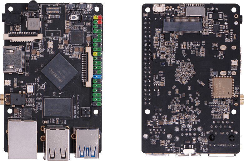
The Quartz64 Model B
Key features include a PCIe x4 open-ended slot (model A) or M.2 slot (model B) using a single Gen2 lane electrically, and the use of LPDDR4 RAM.
The Quartz64 is available in two LPDDR4 system memory options: 4 GB and 8 GB. For booting, there is an eMMC module socket (supporting up to 128 GB) and microSD slot, as well as a footprint to solder on an SPI flash chip. The board is equipped with HDMI, 1x USB 3.0 Type-A host, 3x USB 2.0 host, Gigabit Ethernet, SATA (model A), GPIO Bus, MiPi DSI interface, e-ink interface (model A), eDP interface (model A), touch panel interface (model A), MiPi CSI interface, as well as many other device interfaces such as UART, SPI, I^2^C, for makers to integrate with sensors and other peripherals. Many different Operating Systems (OS) are freely available from the open source community, such as Linux (Ubuntu, Debian, Arch), BSD, and Android.
Getting started
Flashing the device
Natively the board only supports booting the platform firmware from SPI, the eMMC or a microSD card, see boot order. The platform firmware loaded from there (U-Boot, EDK2, …) may then allow loading kernels from additional storage mediums or even the network, and they will have their own boot order.
The board can be booted by flashing your chosen operating system to a microSD card using another device and inserting the microSD card into the Quartz64, see the article Getting started. Flashing the eMMC is possible by booting an operating system from the microSD card and overwriting the eMMC from within the booted operating system, or by using the USB eMMC adapter.
Boot order
The hardware boot order of the Quartz64 is:
- SPI NOR flash
- SPI NAND flash
- eMMC
- microSD card
Pinout
Model “A”
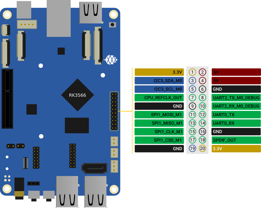
The Quartz64 Model A board pinout
Model “B”
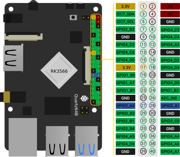
The Quartz64 Model B board pinout
Software
Releases
This page contains a list of all available operating systems for the Quartz64 in alphabetical order, as well as links to other resources.
Software releases
Armbian

Armbian is a base operating system platform for single board computers
- Lightweight Debian or Ubuntu based Linux distribution specialized for ARM development boards
- Each system is compiled, assembled and optimized by Armbian Build Tools
- It has powerful build and software development tools to make custom builds
Download:
Notes:
- Support on Armbian forums https://forum.armbian.com/forum/96-upcoming-hardware-wip/
DietPi

DietPi is a lightweight, yet easy to setup and feature-rich Linux distribution, based on Debian. To find out more about DietPi, please visit the official documentation. Discuss the Quartz64 builds on the PINE64 forum thread.
Download:
- Quartz64 Model A: Direct download from dietpi.com
- Quartz64 Model B: Direct download from dietpi.com
- SOQuartz: Direct download from dietpi.com
| Default credentials | |
|---|---|
root | dietpi |
Manjaro ARM

Manjaro ARM is a user friendly rolling release distribution, based on Arch Linux ARM.
Download:
- Quartz64 Model A: Image on GitHub
- Quartz64 Model B: Image on GitHub
Notes:
Most of the hardware support is already available in the mainline kernel. If some devices doesn’t work it is possible to swap to the linux-quartz64 kernel pacman -S linux-quartz64.
Following desktop options available:
- Gnome
- KDE Plasma
- Mate
- Sway
- XFCE as well as minimal image without desktop.
NetBSD
NetBSD is a free, fast, secure, and highly portable Unix-like Open Source operating system. It relies upon the UEFI support in Tianocore. Before NetBSD 10 is released, the latest version of NetBSD-current should be used.
Download:
- NetBSD daily builds top level from inside here, navigate to a date, and inside the images/ subdirectory are installable images. Use the one called “NetBSD-
-evbarm-aarch64-install.img.gz”.
Notes:
- This image can be written to a supported device, such as the eMMC interface, any USB storage device, NVMe, and PCIe AHCI SATA are all supported with builds after 2022-01-15.
- Currently this can not be shared with the EDK2 port, ie, microSD for EDK2 and some other media for NetBSD.
Plebian
Plebian stands for PINE64 Live Debian and aims to be a fairly vanilla live Debian image for Quartz64 and SOQuartz devices, based on Debian Bookworm.
To flash, run (replace /dev/sdX with your target block device):
$ xzcat imagename.img.xz | sudo dd of=/dev/sdX bs=4M oflag=dsync status=progress
Some quick notes:
- You will be asked to change your password on first login (for what the default login is, read the instructions)
- Root file system is grown to take up the entire space of your boot device
- NetworkManager is used instead of Debian’s interfaces config to be more flexible with what adapters are plugged in and working
- An sshd is started on port 22 with freshly generated keys
Tianocore EDK II port by jmcneill
This (as of 2021-12-30) is a work in progress to enable UEFI enabled systems, and is able to bring up SD, eMMC, USB, PCIe with SATA and NVMe, HDMI, thermal sensors, TRNG, as well as general Cortex A-55 features. Known to work with NetBSD -current, and the ESXi Arm fling version 1.8.
Download:
Notes:
- The microSD card image should be written to an microSD card and installed. Currently, using the same card for the operating system as well may be problematic.
BSP Linux SDK
The *BSP Linux SDK ver 4.19_ for the Quartz64 Model A.
Download:
- Direct download from pine64.org (32.67GB, MD5 of the TAR-GZip file 24554419aec29700add97167a3a4c9ed)
Android SDK
Android 11 SDK
The Android 11 SDK for the Quartz64 Model A SBC.
Download:
- Direct download from pine64.org (79.00GB, MD5 of the TAR-GZip file 77c2ff57ea3372fb04da7fb49e17d12b)
- Just the boot blobs (<1MB): https://wiki.pine64.org/wiki/File:Rk35-blobs.tar.gz
Android 11 Production Test Builds
Android 11 Stock
The Android 11 Stock images for eMMC boot for the Quartz64 Model A. This is test build that was used during product testing.
Download:
- Stock image for the 8GB eMMC module from pine64.org (819MB, MD5 of the Gzip file e4365753e584d9fce1b8f10f095eede6, build 20210604)
- Stock image for the 16GB eMMC module from pine64.org (1.10GB, MD5 of the Gzip file 491c5f7744b0ca0b74ae76e607051836, build 20210604)
- Stock image for the 32GB eMMC module from pine64.org (846MB, MD5 of the Gzip file 47a6f0cdac8bad06cb920743849a8894, build 20210604)
- Stock image for the 64GB eMMC module from pine64.org (884MB, MD5 of the Gzip file 4e2fed6f5db0d55afdc8a142fc0c4fe1, build 20210604)
Notes:
- Write the disk images to the eMMC modules using the USB adapter, for example using
dd. - Please allow 3-5 minutes boot up time on first time for initialization.
Android 11 Production Test Build
The Android 11 Production Test Build for the Quartz64 model A for eMMC boot using ROCKChip tools method. This is a test build that was used during product testing.
Download:
- Direct download from pine64.org (812MB, MD5 of the Gzip file 800f867fdd0d1b2bd7822c156b6067e3, build 20210604)
Notes:
- Please unzip first and then using Rockchip Android tool ver 2.84 to flash in
- For Windows OS environment please install the DriverAssistant v5.11 driver first
- The OTG port located at top USB 2.0 port on top of USB 3.0 port, needs USB type A to type A cable.
- Please allow 3-5 minutes boot up time on first time for initialization
Android 13 SDK
The Android 13 SDK for the Quartz64 Model “Zero” SBC.
Download:
- Direct download from pine64.org (111GB, MD5 of the TAR-GZip file 0cd965cf68145cc62876d50f320a715a)
Android 13 Stock
The Android 13 Stock images for eMMC boot for the Quartz64 Model Zero. This is test build.
Download:
- Direct download from pine64.org (765MB, MD5 of the Gzip file 00086005b07b23b8de06fd0c9f8c6816, build 20240606)
Notes:
- Please unzip first and then using Rockchip Android tool ver 3.13 to flash in
- For Windows OS environment please install the DriverAssistant v5.11 driver first
- The OTG port located on USB 3.0 port, needs USB type A to type A cable.
- Please allow 3-5 minutes boot up time on first time for initialization
The Android 13 Stock images for SD boot for the Quartz64 Model Zero. This is test build.
Download:
- Direct download from pine64.org (765MB, MD5 of the Gzip file c80d48ba407533734fb6484c25d2a398, build 20240614)
Notes:
- Please unzip first and then using Rockchip SD card program tool ver 1.74 to program SD card
- Please allow 3-5 minutes boot up time on first time for initialization
Building U-Boot
This article guides you through compiling U-Boot for a Quartz64 and SOQuartz device.
Prerequisites
You will need either an x86 machine with an aarch64 cross-compiler installed, or an existing aarch64 system. You will also need the device tree compiler dtc, python3 (including setuptools and pyelftools), swig, GNU make and git.
Arch Linux
On an x86_64 Arch Linux system, you can install the required dependencies with:
pacman -S --needed base-devel aarch64-linux-gnu-gcc aarch64-linux-gnu-binutils git dtc python-setuptools swig python-pyelftools
Debian
On an x86_64 Debian (or derivates such as Ubuntu) system, you can install the required dependencies with:
apt install device-tree-compiler build-essential gcc-aarch64-linux-gnu binutils-aarch64-linux-gnu make python3 python3-dev libssl-dev python3-pyelftools python3-setuptools swig git
Fetching the repositories
Use git to clone the mainline U-Boot repository into the directory u-boot:
git clone https://source.denx.de/u-boot/u-boot.git
You can use git checkout _tagname_ inside the u-boot directory to check out a specific git tag (release), you can list all of them with git tag -l (but do keep in mind we only have device support since v2023.10).
Then, also use git to clone the rockchip firmware binaries repository into the directory rkbin:
git clone https://github.com/rockchip-linux/rkbin.git
Setting up your environment
Next, we need to set two environment variables: ROCKCHIP_TPL for the DRAM init binary, and BL31 for the ARM Trusted Firmware binary.
cd u-boot
export ROCKCHIP_TPL="$(ls ../rkbin/bin/rk35/rk3566_ddr_1056MHz_v*.bin | sort | tail -n1)"
export BL31="$(ls ../rkbin/bin/rk35/rk3568_bl31_v*.elf | sort | tail -n1)"
Configuring U-Boot
First, we need to use the right default config for our device. Please choose defconfig from the following table depending on your device:
| Board | defconfig |
|---|---|
| Quartz64 Model A | quartz64-a-rk3566_defconfig |
| Quartz64 Model B | quartz64-b-rk3566_defconfig |
| SOQuartz on Model A | soquartz-model-a-rk3566_defconfig |
| SOQuartz on Blade | soquartz-blade-rk3566_defconfig |
| SOQuartz on CM4 I/O Board | soquartz-cm4-rk3566_defconfig |
In the u-boot directory with your environment variables set, run:
make CROSS_COMPILE=aarch64-linux-gnu- [defconfig]
with [defconfig] being the value from the previous table.
Building U-Boot
In the u-boot directory, after configuring, and with your environment variables set, run:
make CROSS_COMPILE=aarch64-linux-gnu- -j$(nproc)
This will output a u-boot-rockchip.bin, which is your freshly built SPL+U-Boot combined image.
Installing Arch Linux ARM
The articles explains the installation of Arch Linux ARM on the Quartz64.
Commands to be run as a normal user are prefixed with $, commands to be run as root are prefixed with #. We assume your target device is /dev/sdX, adjust accordingly.
Partitioning The Block Device
Here we assume your block device is /dev/sdX, adjust as needed.
Create a new partition table:
# parted -s /dev/sdX mklabel gpt
Create the partitions for loader and u-boot:
# parted -s /dev/sdX mkpart loader 64s 8MiB
# parted -s /dev/sdX mkpart uboot 8MiB 16MiB
Create the partition for u-boot’s environment:
# parted -s /dev/sdX mkpart env 16MiB 32MiB
Create the “efi” boot partition and mark it as bootable:
# parted -s /dev/sdX mkpart efi fat32 32MiB 544MiB
# parted -s /dev/sdX set 4 boot on
Create the root partition:
# parted -s /dev/sdX mkpart root ext4 544MiB 100%
Creating The File Systems
Now create the file systems for boot and root:
# mkfs.vfat -n "efi" /dev/sdX4
# mkfs.ext4 -L "rootfs" /dev/sdX5
Fetching and Flashing U-Boot
For this we’ll use the precompiled idblock and u-boot from pgwipeout’s CI.
Go to https://gitlab.com/pgwipeout/quartz64_ci/-/pipelines and click the three dots, download the merge-job artifacts.
Unzip them:
$ unzip artifacts.zip
Flash idblock.bin and uboot.img:
# dd if=artifacts/idblock.bin of=/dev/sdX1
# dd if=artifacts/uboot.img of=/dev/sdX2
Fetching The Root File System Tarball
Fetch the root filesystem tarball and the PGP signature
$ wget -N http://os.archlinuxarm.org/os/ArchLinuxARM-aarch64-latest.tar.gz{,.sig}
Fetch the gpg keys:
$ curl 'https://keyserver.ubuntu.com/pks/lookup?op=get&search=0x68b3537f39a313b3e574d06777193f152bdbe6a6' | gpg --import=-
Compare the key ID provided in the above command with the one listed here: https://archlinuxarm.org/about/package-signing (Take good note of the domain and HTTPS)
Verify the tarball’s authenticity
$ gpg --verify ArchLinuxARM-aarch64-latest.tar.gz.sig
Installing The Root File System
# mount /dev/sdX5 /mnt/alarm-root
# mkdir /mnt/alarm-root/boot
# mount /dev/sdX4 /mnt/alarm-root/boot
# bsdtar -xpf ArchLinuxARM-aarch64-latest.tar.gz -C /mnt/alarm-root
Editing fstab
Find your partition UUIDs for both partitions using lsblk:
$ lsblk -o NAME,SIZE,MOUNTPOINTS,PARTUUID
In /mnt/alarm-root/etc/fstab, put the lines
PARTUUID=_root-uuid-here_  /       ext4    defaults        0       1
PARTUUID=_boot-uuid-here_  /boot   vfat    defaults        0       2
with your UUIDs in place of the placeholder.
Writing extlinux.conf
Create a /mnt/alarm-root/boot/extlinux/extlinux.conf with these contents:
default l0
menu title Quartz64 Boot Menu
prompt 0
timeout 50
 label l0
menu label Boot Arch Kernel
linux /Image
fdt /dtbs/rockchip/rk3566-quartz64-a.dtb
append initrd=/initramfs-linux.img earlycon=uart8250,mmio32,0xfe660000 console=ttyS2,1500000n8 root=LABEL=rootfs rw rootwait
For Model B
Kernel 5.18 and 5.19 do not yet have the Quartz64 Model B device tree, however, you can add it manually to your install and adjust extlinux.conf:
Download it from here: https://overviewer.org/~pillow/up/5f1fabef1b/rk3566-quartz64-b.dtb (this is just linux-next with sd card speed changed to sd-uhs-sdr50)
Copy it to /mnt/alarm-root/boot/dtbs/rockchip/rk3566-quartz64-b.dtb
Then adjust your /mnt/alarm-root/boot/extlinux/extlinux.conf*’s fdt* line as follows:
fdt /dtbs/rockchip/rk3566-quartz64-*b*.dtb
Finishing Up
Once done, unmount the partitions:
# umount /mnt/alarm-root/boot
# umount /mnt/alarm-root
Booting And Finishing Setup
Hook up your UART dongle to your Quartz64, open a serial terminal at 1.5mbauds. Install the SD card or eMMC module inside the Quartz64, and plug in the power.
Once you hit a login shell, log in as root with password root and run:
# pacman-key --init
# pacman-key --populate archlinuxarm
You are now ready to use Arch Linux ARM! Either delete or rename (and move the homedir of) the alarm user, and you’re all set. Don’t forget to install things like sudo and setting up sudo groups and such.
Installing Debian
It is possible to install Debian onto eMMC of the Quartz64 from the pgewipout quartz64_ci imaged to a Micro SDcard, or vice versa.
This might be useful if you don’t have an eMMC to USB adapter or if the board is inside a case which doesn’t allow eMMC removal.
Download artifacts merge-job:archive from https://gitlab.com/pgwipeout/quartz64_ci/-/pipelines
Unpack zip file
Image to a Micro SDcard present in your PC as /dev/sdX:
sudo -i; xzcat images/rk3566-quartz64-a.dtb.img.xz > /dev/sdX

sudo sync
Boot quartz64-a from microSD card
At boot menu select 1 (Buildroot-recovery)
parted -s /dev/mmcblk1 mklabel gpt
parted -s /dev/mmcblk1 mkpart loader 64s 8MiB
parted -s /dev/mmcblk1 mkpart uboot 8MiB 16MiB
parted -s /dev/mmcblk1 mkpart env 16MiB 32MiB
parted -s /dev/mmcblk1 mkpart efi fat32 32MiB 544MiB
parted -s /dev/mmcblk1 set 4 boot on
parted -s /dev/mmcblk1 mkpart root ext4 544MiB 100%

dd if=/dev/mmcblk0p1 of=/dev/mmcblk1p1
dd if=/dev/mmcblk0p2 of=/dev/mmcblk1p2
dd if=/dev/mmcblk0p3 of=/dev/mmcblk1p3

mkdosfs -F 32 -n "efi" /dev/mmcblk1p4

mke2fs -L "rootfs" /dev/mmcblk1p5

sync

reboot
At boot menu select 2 (Debian-Installer)
choose manual partitioning
set partition #5 of mmcbkl1 to be /, format to ext4 and complete the installation
reboot (installer will do this anyway)
mkdir /mnt/mmcblk0p5
mkdir /mnt/mmcblk1p4
mkdir /mnt/mmcblk1p5

mount /dev/mmcblk0p5 /mnt/mmcblk0p5
mount /dev/mmcblk1p4 /mnt/mmcblk1p4
mount /dev/mmcblk1p5 /mnt/mmcblk1p5

cp -a /mnt/mmcblk0p5/dtbs /mnt/mmcblk1p4/
cp /mnt/mmcblk0p5/vmlinuz /mnt/mmcblk1p4/

mkdir /mnt/mmcblk1p4/extlinux

touch /mnt/mmcblk1p4/extlinux/extlinux.conf

echo 'label Debian on eMMC' >> /mnt/mmcblk1p4/extlinux/extlinux.conf
echo 'linux /vmlinuz' >> /mnt/mmcblk1p4/extlinux/extlinux.conf
echo 'fdt /dtbs/rockchip/rk3566-quartz64-a.dtb' >> /mnt/mmcblk1p4/extlinux/extlinux.conf
echo 'append earlycon=uart8250,mmio32,0xfe660000 console=ttyS2,1500000n8 root=/dev/mmcblk1p5 rootwait' >> /mnt/mmcblk1p4/extlinux/extlinux.conf

cp /mnt/mmcblk0p5/kernel-modules.tar.gz /mnt/mmcblk1p5/root/
The following lines (upto adding the boot partition to fstab) are optional. Debian will boot just fine if the boot partition isn’t in fstab and you may prefer to manually mount it when you want to change the kernel:-
blkid /dev/mmcblk1p4
The output will show the UUID of your boot partition:-
/dev/mmcblk1p4: LABEL_FATBOOT=“efi” LABEL=“efi” UUID=“5985-9C7B” BLOCK_SIZE=“512” TYPE=“vfat” PARTLABEL=“efi” PARTUUID=“93226dfa-53af-4400-8aab-239ff7900dd0”
echo 'UUID=UUID_from_above /boot    vfat    defaults        0       1' >> /mnt/mmcblk1p5/etc/fstab

chroot /mnt/mmcblk1p5

dpkg -l |grep image
To show which kernel images Debian has installed:-
ii linux-base 4.6 all Linux image base package
ii linux-image-4.19.0-18-arm64 4.19.208-1 arm64 Linux 4.19 for 64-bit ARMv8 machines (signed)
ii linux-image-arm64 4.19+105+deb10u13 arm64 Linux for 64-bit ARMv8 machines (meta-package)
Uninstall them:
dpkg -P linux-image-4.19.0-18-arm64 linux-image-arm64

cd /root

tar -xzvf kernel-modules.tar.gz

mv lib/modules /lib/

exit

halt
Remove MicroSD card and boot into eMMC.
Development
This page documents the current status of software support for the Quartz64 single-board computer, and provides links to resources to help prospective contributors get started. Information is kept current on a best-effort basis as various patches get accepted into the kernel.
Overview
Upstreaming Status
| Function | Status | Component | Notes | Applies To | |
|---|---|---|---|---|---|
| Video Output | Linux Mainline | rockchipdrm/VOP2 | As of 5.19-rc1Source,Also featured in Phoronix ArticleSource, 4k@30 support and other improvements in 6.4-rc1Source | ||
| Needs porting | rockchip-edpphy-naneng | Downstream: Source and Source Coordinate any porting with Rockchip first | |||
| Linux Mainline | dw-mipi-dsi-rockchip | As of 6.1Source | |||
| 3D Acceleration | Linux Mainline | Upstream Mesa | panfrost | As of 5.18Source | |
| Video Decode | Linux Mainline | GStreamer only, no ffmpegSource | hantro using v4l2-requests | VDPU121 handling 1080p MPEG-2, VP8 and H.264. Mainline as of 5.19Source | |
| Needs writing | rkvdec2 using v4l2-requests | VDPU346 handling 4K H.265, H.264 and VP9 | |||
| Needs writing | rkdjpeg using v4l2-requests | VDPU720 handling JPEG, User:CounterPillow is working on this | |||
| Video Encode | Linux Mainline | GStreamer only | JPEG on VEPU121 | Hantro-based. Mainline as of 6.1Source | |
| Needs writing | ? | H.264 on VEPU121 | Hantro-based | ||
| Needs writing | ? | VP8 on VEPU121 | Hantro-based | ||
| Needs writing | ? | H.264 on VEPU540 | rkvenc-based | ||
| Needs writing | ? | H.265 on VEPU540 | rkvenc-based | ||
| Audio | Linux Mainline | rockchip-i2s-tdm | As of 5.16Source | ||
| Linux Mainline | rockchip-spdif | As of 5.15Source | |||
| Linux Mainline | rk817-codec | As of 5.14Source. | Quartz64 Model A/B | ||
| Bootloader | In reviewSource | TF-A | |||
| Merged | U-Boot | #mainline_u_boot_work[See below]. Quartz64 and SOQuartz as of v2023.10-rc2Source | |||
| In progressSource | Tianocore EDK II | ||||
| Device Tree | Linux Mainline | Quartz64 Model A | As of 5.16Source | Quartz64 Model A | |
| Linux Mainline | Quartz64 Model B | As of 5.19Source | Quartz64 Model B | ||
| Linux Mainline | SOQuartz | As of 5.19Source | SOQuartz | ||
| Linux Mainline | PineNote | As of 5.18Source | PineNote | ||
| Gigabit Ethernet | Linux Mainline | rk3566-gmac | As of 5.14Source | ||
| Linux Mainline | yt8511-phy | As of 5.14Source | |||
| IOMMU | Linux Mainline | rockchip-iommu | As of 5.14Source | ||
| GPIO | Linux Mainline | gpio-rockchip | As of 5.15Source | ||
| pinctrl | Linux Mainline | ||||
| Thermal Regulation | Linux Mainline | rockchip-thermal | As of 5.14Source | ||
| PCIe | Linux Mainline | pcie-dw-rockchip | As of 5.15Source | ||
| Power Management | Linux Mainline | rockchip-pm-domains | As of 5.14Source | ||
| Voltage Control | Linux Mainline | rk3568-pmu-io-voltage-domain | As of 5.15Source | ||
| SPI | Linux Mainline | spi-rockchip | As of 5.14Source.Necessary device tree changes in review. | ||
| Battery | Linux Mainline | rk817-charger | As of 6.1Source | Quartz64 Model A, PineNote | |
| Microphone | Linux Mainline | rockchip-saradc | As of 5.15Source. Headphone jack mic seems to connect to SARADC_VIN2_HP_HOOK, so I’m pretty sure that the dtsi and driver changes are needed for that mic to work | ||
| USB 2.0 | Linux Mainline | rockchip-usb2phy | As of 5.17Source | ||
| e-Ink | In review (RFC)Source | rockchip-ebc | A DRM driver is available here; See also RK3566 EBC Reverse-Engineering | ||
| Combo PHY | Linux Mainline | naneng-combphy | As of 5.18Source. Still requires DTS changes | ||
| RGA | Linux Mainline; Could be improved | rockchip-rga | As of 6.5Source. Note that there’s still a ‘4GB’ problem and it’s implementations has room for improvements (to put it midly Source and Source) | ||
| Fan Controller | Needs writing | gp7101 | Someone should write a pwm driver for it so we can then use pwm-fan | SOQuartz Blade | |
| CSI Camera | Needs porting | rkisp | Downstream: Source | ||
| Linux Mainline | rockchip-inno-csidphy | As of 6.1Source | |||
| NPU | Needs writing | Downstream version is a closed source SDK and open source kernel module rknpu. Major undertaking to reimplement this as Linux does not (yet) appear to have a generic architecture for neural accelerators. | |||
| Crypto | Needs porting | rk-crypto v2 | Downstream driver (link) doesn’t include a rk3568 compatible either, but the TRM shows that it seemingly matches. | ||
| TRNG | In reviewSource | rockchip-rng | |||
| Wi-Fi | Needs porting | bes2600 | A downstream driver is available but it makes use of some custom Rockchip interfaces and is designed for older kernels, plans are being made to port it to DKMS. | PineTab 2 | |
| Linux Mainline | brcmfmac | Quartz64 Model B |
Current Status
The following sections give an overview over the current status of different parts of the board. Some parts are waiting on a driver to be written or ported, others only need various adjustments.
According to pgwipeout, I/O device performance is within expected ranges now.
Working
- eMMC
- SDMMC0 (SD cards)
- GMAC (Gigabit Ethernet)
- USB 2.0
- SATA 2
- SATA 3
- UART
- UART 0 (Pi-bus)
- UART 1 (Bluetooth)
- UART 2 (Pi-bus, debug)
- Video Decode
- VP8
- H.264
- Video Encode
- JPEG (it’s pretty bad)
- Battery
- GPU
- Video Output
- HDMI
- DSI
- Audio
- Analog audio works
- SPDIF works
- HDMI works
- SPI — works, user needs to modify device tree to add devices
- I^2^C — works, user needs to modify device tree to add devices
Partially Working
- PCI-Express Controller — everything but devices that need cache coherency (e.g. dGPUs) should work
- User:CounterPillow noticed some weirdness with NVMe devices disconnecting during heavy write operations, likely down due to power draw on one of the rails as the same sustained bandwidth could be achieved with a different PCIe device with no issue.
- SDMMC1 (Wi-Fi) — AP6256 working, BL602 needs some work to make it flash firmware
- GIC — needs errata published by Rockchip to get upstream to add device-specific workarounds ^link:https://lore.kernel.org/linux-rockchip/CAMdYzYrQ5f-mv_VmTq_CRf9tR=\j3mwRpKHNLmPFgCF9whsGFRw@mail.gmail.com/[link]^
Confirmed Broken
USB 3.0 (applies to Model A only) — only works with very short cables and depends on the device. This is due to a hardware design issue relating to the coupling capacitors needed for SATA, which shares the same lines as USB 3.0.Hardware design changes have been suggested to engineers, it’s in their hands now.- Fixed in newer revisions by leaving SATA unpopulated
- RGA — only works with memory ≤ 4 GiB, because Rockchip didn’t make the address registers larger. Oopsie.
Needs Testing
- E-Paper
- Microphone Input
- CSI — needs CIF driver
- eDP — needs PHY driver and controller driver
TODO
ebc-dev Reverse Engineering and Development
The driver for the eInk panel needs to both be reverse engineered and then rewritten as C. In its current form, it is mostly an assembly dump produced by gcc with debug symbols. See RK3566 EBC Reverse-Engineering for details.
Investigate MCU
The RK3566 comes with an integrated RISC-V microcontroller (MCU). It communicates with the A55 host through the Mailbox system driven by the rockchip-mailbox driver. Since this MCU would be quite useful for things such as low power standby mode, investigating how it can be turned on and have firmware flashed to it should greatly enhance the power saving features of the PineNote.
The user liamur did some investigation into the MCU and found that it is disabled by TF-A on suspend, and doesn’t reside in a low-power part of the RK3566 anyway. It does however have access to most of the chip and could be used as (for example) a real-time coprocessor.
Mainline U-Boot Work
We currently use the “downstream” Rockchip U-Boot, which is based on an old version of U-Boot and contains vendor specific patches that have not undergone the same level of code review as they’d have done had they been submitted upstream.
While the lack of ATF sources means that using mainline U-Boot would still require the use of Rockchip provided binaries for the firmware, even with Rockchip blobs, a more modern version of U-Boot will be much nicer to use.
Mainline U-Boot contains good enough support for the RK3566 SoC used on the Quartz64 as of v2023.07 and have support for Quartz64 and SOQuartz as of v2023.10-rc2. Drivers for ethernet GMAC and Motorcomm PHY are supported as of v2024.01-rc1.
Things that could be done
This list is non-exhaustive as we don’t exactly know how much is missing
- Port a basic VOP2 driver to get a framebuffer from u-boot
List of Useful Resources for this Task
- Downstream Rockchip U-Boot repository with Quartz64 specific patches: https://gitlab.com/pgwipeout/u-boot-rockchip/-/tree/quartz64
- Mainline Rockchip custodian U-Boot repository: https://source.denx.de/u-boot/custodians/u-boot-rockchip
- U-Boot Mailing List: https://lists.denx.de/listinfo/u-boot
eDP Driver Porting
The eDP PHY driver and controller driver needs to be ported, brought into shape and submitted with proper commit attribution to the Rockchip authors.
User:CounterPillow has experimentally ported stuff, but it’s currently not working.
Linux Kernel Config Options
CONFIG_SND_SOC_ROCKCHIP_I2S_TDM- for Analog and HDMI audio
CONFIG_SND_SOC_RK817- for Analog audio on the Model A
CONFIG_STMMAC_ETH- Ethernet
CONFIG_DWMAC_ROCKCHIP- Ethernet
CONFIG_MOTORCOMM_PHY- Ethernet PHY for Model A, set this one to Y, m won’t work out of the box if the generic PHY driver is y and binds first. Alternatively tell users in board-specific setup instructions to force including the
motorcommmodule in initramfs if you set it to m.
- Ethernet PHY for Model A, set this one to Y, m won’t work out of the box if the generic PHY driver is y and binds first. Alternatively tell users in board-specific setup instructions to force including the
CONFIG_REALTEK_PHY- Ethernet PHY for Model B
CONFIG_MMC_DW- MMC/SD
CONFIG_MMC_DW_ROCKCHIP- MMC/SD
CONFIG_MMC_SDHCI_OF_DWCMSHC- MMC/SD
CONFIG_PCIE_ROCKCHIP_DW_HOST- PCIe
CONFIG_PHY_ROCKCHIP_NANENG_COMBO_PHY- PHY for PCIe/SATA/USB3
CONFIG_DRM_PANFROST- GPU
CONFIG_SND_SOC_ROCKCHIP_SPDIF- SPDIF audio
CONFIG_ROCKCHIP_DW_HDMI- HDMI PHY
CONFIG_PHY_ROCKCHIP_INNO_DSIDPHY- MIPI DSI DPHY
CONFIG_ROCKCHIP_VOP2- Video output
CONFIG_ARCH_ROCKCHIP- General SoC support
CONFIG_ROCKCHIP_PHY- General SoC support
CONFIG_PHY_ROCKCHIP_INNO_USB2- USB 2
CONFIG_RTC_DRV_RK808- Real-time Clock
CONFIG_COMMON_CLK_RK808- Real-time Clock
CONFIG_MFD_RK808- Various things relating to the RK817 chip
CONFIG_CHARGER_RK817- RK817 charger
CONFIG_REGULATOR_RK808- Voltage regulators
CONFIG_ROCKCHIP_PM_DOMAINS- Power management domains
CONFIG_GPIO_ROCKCHIP- GPIO support
CONFIG_PINCTRL_ROCKCHIP- GPIO and general SoC support
CONFIG_PWM_ROCKCHIP- PWM support
CONFIG_ROCKCHIP_IOMMU- IOMMU support
CONFIG_ROCKCHIP_MBOX- Mailbox support (for communication with MCU)
CONFIG_ROCKCHIP_SARADC- Analog-to-digital conversion support, for e.g. microphones
CONFIG_ROCKCHIP_THERMAL- Temperature sensor and thermal throttling support
CONFIG_SPI_ROCKCHIP- SPI support
CONFIG_VIDEO_HANTRO_ROCKCHIP- Hardware video decoder support
CONFIG_ROCKCHIP_IODOMAIN- General SoC support so your I/O pins have the right voltage
CONFIG_COMMON_CLK_ROCKCHIP- Common clock support
CONFIG_PHY_ROCKCHIP_INNO_CSIDPHY- MIPI CSI DPHY
CONFIG_I2C_RK3X- I2C support
Resources
Repositories
- pgwipeout’s kernel tree
- BSP based development effort for SPL/U-Boot and Linux
- Image CI pipeline aimed at developers
- Rockchip U-Boot
- Downstream rockchip-linux kernel tree
- Tianocore EDK II port for UEFI on Quartz64
- Mainline U-Boot Port by pgwipeout
Other
- Rockchip-SoC Patchwork Page
- Rockchip Kernel Mailing List Archive
Board/SoC Documentation
Booting
Boot Order
The RK3566 boot ROM will search for a valid ID BLOCK in the following order on the support boot media:
- SPI NOR flash
- SPI NAND flash
- eMMC
- SD-Card
If this fails, the boot ROM will initialize the USB0 port and wait for a connection from the Rockchip flash/boot tools.
Bootloader Flashing
As per pgwipeout’s commit message:
- Make a partition named
ubootas partition number 1 at 8 MiB to 16 MiB dd if=idblock.bin of=/dev/_<mmc/sd>_ seek=64dd if=uboot.img of=/dev/_<mmc/sd>_1
Efforts
Information and resources of the ongoing development effort for the Quartz64 can be found on the Development page, where the current status of various board functions can be found, and whether they have landed in upstream.
Frequently Asked Questions
Do I Need A Fan/What Heatsink Do I Need?
You don’t need a fan. The 20mm medium heatsink for Model A is plenty enough. For Model B, the fan type heatsink will do fine.
Can This Run A Minecraft Server?
Yes! Sort of. Testing on an 8GB Model A with PaperMC, User:CounterPillow was able to out-row world generation in a boat with just one player online, but aside from the slow world gen (which can be pre-generated) the server handled things like TNT explosions and mobs fine. It’ll probably do okay with 1-3 players.
Do I Need The 5A Power Supply For Model A?
You only need the 5A power supply for Model A if you plan on connecting hard disk drives to the 12V header on the board.
How Much Power Does It Consume?
For Model B, it’s <2W in idle (powertop tunables not set), and <5W under full CPU load (stress-ng -c4). Model A will be similar as it’s the same SoC.
Troubleshooting
Stability/Boot Issues With Missing Battery Shunt
If there is no battery plugged into the board, the jumper labelled “ON/OFF_BATT” must be in place. If this is set wrong, stability issues such as failures to boot will occur.
No Ethernet Connectivity
Make sure the kernel is built with CONFIG_MOTORCOMM_PHY set to y. Building it as a module (m) and then relying on module auto-loading is unlikely to work, because if the generic PHY driver is built in it will bind to the PHY first, unless you include the motorcomm module in your initramfs.
Note: Starting with Debian’s 6.1~rc3-1~exp1 kernel the module is included, but set to m and I (Diederik) have verified that it gets included in the initramfs and works on Model-A and Model-B with the Quartz64 images.
“Model A” Acrylic Case Doesn’t Fit
The Quartz64 does not really fit onto the bottom plate of the Model A Acrylic Open Enclosure. This is because the “Mic” connector at the bottom of the board interferes with one of the posts. A workaround is to find out which post that is (you have a 50% chance of guessing it right, accounting for rotating the board) and then filing away the corner of the post pointing inwards by a few millimeters.
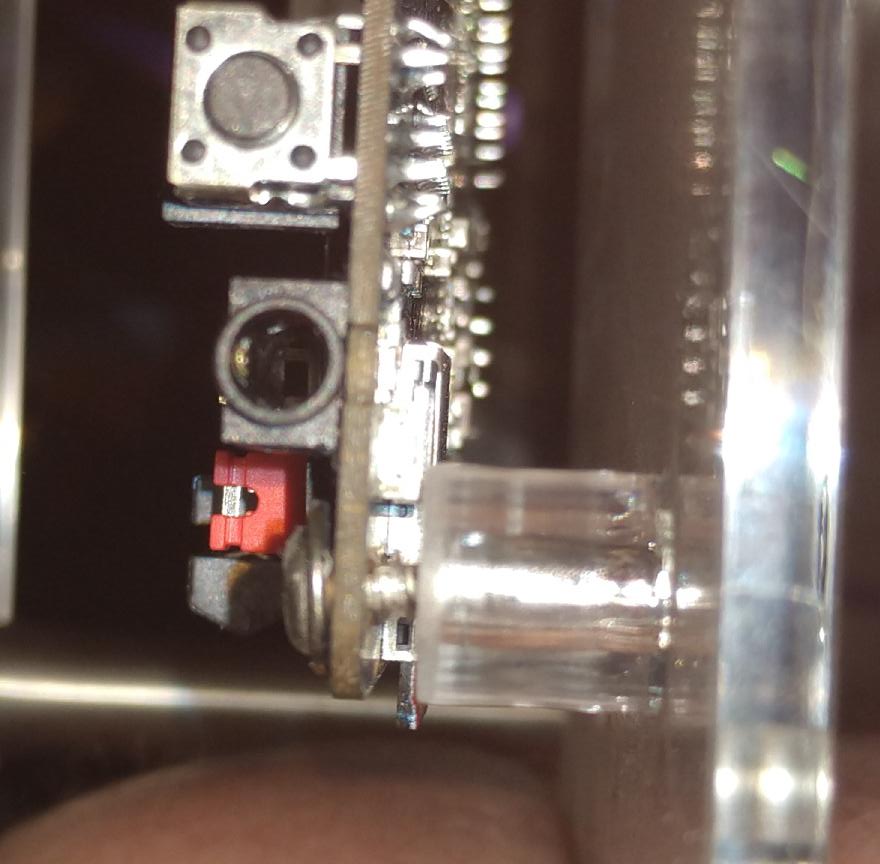
An alternate solution may be to place plastic spacers with a smaller outer diameter in between the acrylic bottom plate posts and the SBC board.
No GPU Acceleration with Debian “Bullseye” Userland
Debian Bullseye ships a Mesa version that is too old to contain the required patches for the RK356x SoC’s GPU. Upgrade to Bookworm.
Wireless Connectivity Doesn’t Work
ROCKPro64 wireless module may have CYW43455 or CYW43456 chips on board (not sure if this is the same for Quartz64 model B). Both chips are supported by brcmfmac Wi-Fi driver and btbcm Bluetooth driver.
For CYW43455 drivers attempt to load /lib/firmware/brcm/brcmfmac43455-sdio.bin for Wi-Fi and /lib/firmware/brcm/BCM4345C0.hcd for Bluetooth. Corresponding firmware files for CYW43456 are /lib/firmware/brcm/brcmfmac43456-sdio.bin and /lib/firmware/brcm/BCM4345C5.hcd.
On Manjaro firmware files for both Bluetooth and Wi-Fi on CYW43456 on are provided by ap6256-firmware package (pacman -S ap6256-firmware).
However for CYW43455 wi-fi firmware is in the linux-firmware package and bluetooth is in the firmware-raspberrypi (pacman -S linux-firmware firmware-raspberrypi). linux-firmware package is missing device specific symlinks for quartz64-a. To create them execute:
# ln -s brcmfmac43455-sdio.bin /lib/firmware/brcm/brcmfmac43455-sdio.pine64,quartz64-a.bin
# ln -s brcmfmac43455-sdio.AW-CM256SM.txt /lib/firmware/brcm/brcmfmac43455-sdio.pine64,quartz64-a.txt
As of 2022-10-19 device tree in mainline kernel for Quartz64 model A has wrong configuration for the Bluetooth driver. Patch is submitted to the LKML and accepted and included upstream in 6.1-rc7. It’s possible to modify dtb file provided by the current kernel using device tree compiler to enable Bluetooth or perform make dtbs in the patched kernel tree to get updated dtb file (arch/arm64/boot/dts/rockchip/rk3566-quartz64-a.dtb). Issue manifests itself with following errors in dmesg:
command 0x0c03 tx timeout
Bluetooth: hci0: BCM: Reset failed (-110)
How-Tos
Connect Debug UART
The easiest way to get debug output is to connect a 3.3V 1.5mbaud capable UART adapter to the board.
To connect it, connect the ground lead to pin 6, and the RX/TX leads to pins 8 and 10 (consider swapping them if you get no output, things are often mislabeled). These pins are “UART2” in the above GPIO table.
Open a serial terminal at 1500000 bauds, e.g.
$ picocom -b 1500000 /dev/ttyUSB0
Disable Heartbeat LED (Linux)
The flashing LED is called the “heartbeat LED”, it blinks in a heart rhythm like fashion once the kernel is running. To disable it, you can run
# echo none > /sys/class/leds/user-led/trigger
On model A LED device is called “diy-led”, not “user-led”.
On a system with systemd, you can do this as soon as the system is ready to be logged in with a systemd unit like this:
[Unit]
Description=Turn off heartbeat LED
Wants=multi-user.target
After=multi-user.target

[Install]
WantedBy=multi-user.target

[Service]
Type=simple
ExecStart=sh -c 'echo none > /sys/class/leds/user-led/trigger'
Place it in /etc/systemd/system/user-led.service, and run
# systemctl daemon-reload
# systemctl enable user-led.service
Upon rebooting, you will now notice that the heartbeat LED will blink during boot-up, but stops blinking as soon as the multi-user target is reached (i.e. the user can log in).
SATA on model A
On model A USB 3.0 and SATA ports are using the same I/O line and can’t be used simultaneously. By default USB 3.0 is enabled in Linux device tree and SATA is disabled. FDT modifications are required to turn SATA on.
Following script is tested on Manjaro but should work on the other distributions with minimal changes. Device tree compiler package usually provides fdtput command (on Manjaro run: pacman -S dtc)
# cp /boot/dtbs/rockchip/rk3566-quartz64-a.dtb /boot/dtbs/rockchip/rk3566-quartz64-a-sata.dtb
# fdtput -t s -v /boot/dtbs/rockchip/rk3566-quartz64-a-sata.dtb /usb@fd000000 status disabled
# fdtput -t s -v /boot/dtbs/rockchip/rk3566-quartz64-a-sata.dtb /sata@fc400000 status okay
# sed -i 's#^FDT /dtbs/rockchip/rk3566-quartz64-a.dtb$#FDT /dtbs/rockchip/rk3566-quartz64-a-sata.dtb#' /boot/extlinux/extlinux.conf
# systemctl reboot
Using a PCF8574 on Model A
Using a battery on Model A
Connecting a MIPI-DSI display
See Connecting a MIPI-DSI display.
Connecting a MIPI-DSI display
The Quartz64 single-board computers (both Model A and Model B) come with MIPI-DSI ports for connecting a MIPI-DSI compatible display.
This article will go into how to connect the official PINE64 7" LCD Touch Screen Panel and setting up the software. Since this requires a panel driver for each panel, other displays generally are not interchangeable, as they won’t use the same driver compatible (or even have a mainline driver at all!)
Connecting the hardware
When connecting the display, please make sure the board is powered off and unplugged. Failure to do so could make you short out the pins while connecting it!
Model A
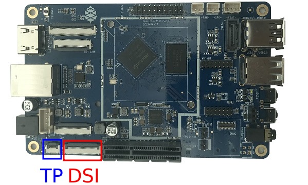
To connect the hardware, lift up the dark flap of the part marked with “DSI” in red in the above picture. Then, insert the flat flex cable with the contacts pointing down (and the blue backing pointing up). In the same fashion, connect the thinner touch panel controller cable to the port marked with “TP” in blue.
For the DSI cable, connect the other end to the small green joiner/adapter board, which you can first connect to the display’s DSI connector, again with the contacts facing down.
For the touch cable, connect the other end to the small green PCB attached to the back of the panel, again paying attention to have the contacts facing downwards (and the blue backing facing upwards).
Model B
TODO: Write this section. Adapter cable is needed.
Setting up the software
For the display to be used, you need to tell the kernel about it by modifying the device tree. The easiest way to go about this is to use device tree overlays.
The kernel needs to be built with CONFIG_DRM_PANEL_FEIYANG_FY07024DI26A30D turned on (either as module or built-in), as that is the driver for this panel.
On Plebian
Use git clone to clone the overlay-examples repository by CounterPillow. Then, grab a copy of the Linux kernel source from kernel.org if you don’t already have one. To build the device tree overlays, run make INCLUDE_DIR=path/to/linux/include in the overlay-examples directory, substituting path/to/linux/include with your path of course.
For Quartz64 Model A, copy build/quartz64a/pine64-lcd-panel.dtbo into your /boot/dtbo/ directory (create it if it doesn’t already exist) and run sudo u-boot-update.
That’s all there is to it, the panel should light up on your next reboot.
Model A: Using a battery
The Quartz64 Model A allows for it to be powered from a single-cell 3.7V lithium-polymer battery. Because of unfortunate incidents, batteries are not easy to ship internationally, so PINE Store does not sell a matching battery for the board.
Pin-out

right
The pins on the board are a JST PH-3 compatible header labelled +VBAT-. As one might guess, the positive wire should be towards the +, and the ground wire towards -. The center pin of the connector is for a temperature probe.
Ways to get a battery
We will now go into various ways one might go about getting a working battery.
Crimping one yourself
You will need:
- an Engineer PA-20 (Amazon Search, eBay Search) or Hozan P-707 (Amazon Search, eBay Search) or similar crimp tool (<$80, good to have around anyway)
- The Hozan P-707 is also comparatively good at crimping “Dupont”-style terminals, in case you find yourself doing that a lot, because it provides round crimping holes in addition to rectangular ones.
- JST PHR-3 receptacles (~$0.05 on digikey)
- 3× JST SPH-002T-P0.5L crimp terminals (~$0.03 on digikey per terminal)
- When ordering from digikey, try to hit the minimum order cost to qualify for free shipping; you’ll get free fast courier shipping with all customs and duties pre-paid.
- a single-cell 3.7V lithium-polymer battery, ideally with a temperature probe
- 2800 mAh Renata ICP606168PRT on Conrad Germany, Conrad Switzerland
- 2000 mAh Adafruit on Adafruit US (no temperature probe, pre-crimped with JST PHR-2; just lift up the plastic tabs and pull out the terminals and shove them back into a PHR-3 connector)
- Aliexpress: try keywords “3.7v lithium battery temperature probe”
Crimp the terminals onto the wires, crimp the strain relief onto the insulation, slide them into the connector until they firmly click in place.
PINE64 18650 battery case
You will need:
- PINE64 Lithium Battery Casing
- an 18650 sized lithium battery (not LiFePo4!)
TODO: Get one of these and document how to use them
Using the battery
Hardware
- Ensure the wires in the connector are in the right order.
- Turn off your Quartz64 Model A.
- Remove the BAT ON/OFF jumper.
- Plug in your battery.
- It is now ready to use if your device tree has been set up correctly.
Caveats
Not all parts of the board can be supplied from the battery. When you use battery as backup power for the board keep in mind that following parts of Quartz64-A will lose power when DCIN loses power:
- 12V Fan connector
- EDP LCD backlight
- 5V power rails on the 20 pin GPIO header
- PCIe socket (both 12V and 3.3V supplies)
- All USB ports except for the black one
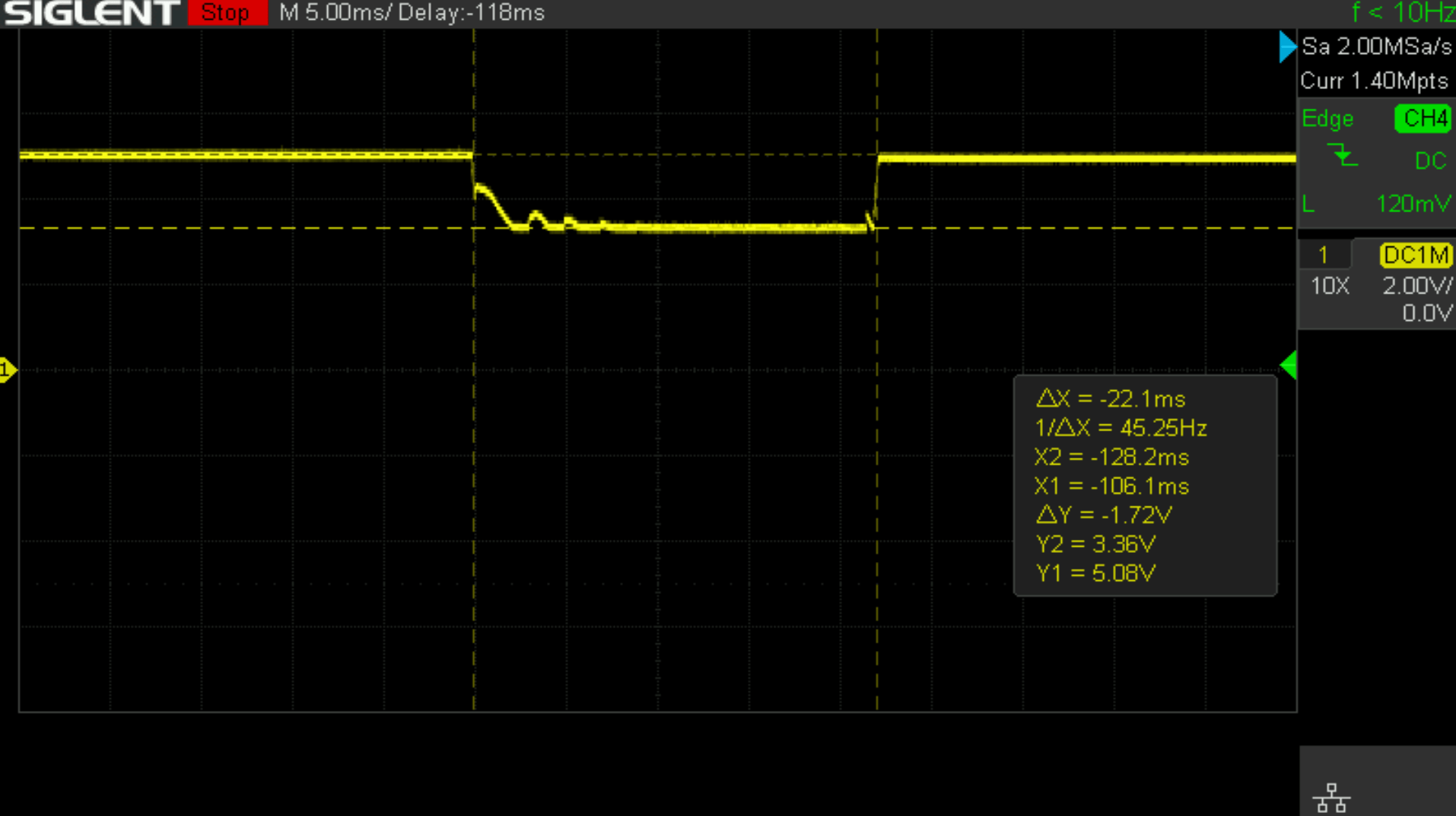
- Black USB port’s VBUS (the one above the USB 3.0 port) will go through a 22ms brownout to approximately VCC_SYS - 0.6V voltage, before the RK817 BOOST regulator kicks in. This will likely cause the connected USB device to reset or have its internal state corrupted.
Software
For the battery to be correctly detected, you will need to edit the device tree to add the charger and battery nodes, like this:
// add this to root node (you may need to modify the values to fit your chosen battery)
battery: battery {
	compatible = "simple-battery";
	charge-full-design-microamp-hours = <6400000>;
	charge-term-current-microamp = <200000>;
	constant-charge-current-max-microamp = <2000000>;
	constant-charge-voltage-max-microvolt = <4200000>;
	factory-internal-resistance-micro-ohms = <117000>;
	voltage-max-design-microvolt = <4200000>;
	voltage-min-design-microvolt = <3200000>;

	ocv-capacity-celsius = <20>;
	ocv-capacity-table-0 =  <4200000 100>, <4054000 95>, <3984000 90>, <3926000 85>,
				<3874000 80>, <3826000 75>, <3783000 70>, <3746000 65>,
				<3714000 60>, <3683000 55>, <3650000 50>, <3628000 45>,
				<3612000 40>, <3600000 35>, <3587000 30>, <3571000 25>,
				<3552000 20>, <3525000 15>, <3492000 10>, <3446000 5>,
				<3400000 0>;
};

// add this to &rk817 node
rk817_charger: charger {
	monitored-battery = <&battery>;
	rockchip,resistor-sense-micro-ohms = <10000>;
	rockchip,sleep-enter-current-microamp = <300000>;
	rockchip,sleep-filter-current-microamp = <100000>;
};
You will also need to make sure that CONFIG_CHARGER_RK817 is enabled in your kernel.
Model A: using a PCF8574
In this article, we’ll go over how to hook up a PCF8574 I^2^C I/O extender to a Quartz64 Model A single-board computer, including what device tree changes to make and how to control it.
Introduction to the PCF8574
The PCF8574 is a fairly ubiquitous GPIO extender that communicates through the I^2^C bus. You can find modules featuring it from many vendors on the usual marketplaces for cheap. It exposes 8 additional GPIO lines, and can be daisy chained to up to 8 devices, giving you an additional 64 GPIO outputs. Combining it with 8 PCF8574A modules will actually push this to a total of 128 GPIO outputs added to your board!
The PCF8574 has a mainline Linux driver, meaning that you do not need to use I^2^C directly to control it; it will just appear as another /dev/gpiochip_<n>_ device. A lot of Raspberry Pi focused guides for this chip get this precise thing wrong actually, and have the user manually fiddle with the bus.
Device tree changes
To control the chip, you’ll need to modify your board’s device tree—a description of its hardware for devices that don’t automatically enumerate—so that the kernel knows how to load the driver.
There are two ways to edit your device tree. Either you can manually edit the base tree, or use device tree overlays.
Device tree overlays
On images/distributions which support device tree overlays in their build of u-boot and the device tree blobs, you can very simply write a device tree overlay. This means your base tree can still change as you update your OS, and there’s no manual intervention needed on your part to have your modification be carried forward.
Your overlay will look something like this:
/dts-v1/;
/plugin/;

&i2c3 {
    #address-cells = <1>;
    #size-cells = <0>;
    status = "okay";

pcf8574: pcf8574@20 {
    compatible = "nxp,pcf8574";
    reg = <0x20>;
    gpio-controller;
    #gpio-cells = <2>;
};
;
You can compile it with dtc -O dtb -o pcf8574.dtbo -@ pcf8574.dts, assuming your input file is called pcf8574.dts.
Installing the overlay depends on your distribution. On Plebian, see DT_OVERLAYS.md.
If you want to use constants and includes in your device tree overlay, you’ll need to pass the file through a C preprocessor with the appropriate include directories. For an example of a build system that does this, please consult the Makefile of CounterPillow’s overlay-examples repository.
Manually editing the base tree
The easiest way to go about this is to get a copy of the Linux kernel source code from https://kernel.org that matches your kernel version (uname -a), as the device tree definitions live in the Linux kernel repository. Technically, device trees should be compatible across kernel versions, but I wouldn’t gamble on it.
Once you have the kernel source, you can use your local configuration: run zcat /proc/config.gz > .config inside the top-level directory of the Linux kernel source tree to use your running kernel’s configuration. Then run make xconfig (or one of the other non-graphical alternatives, like nconfig or menuconfig), save the configuration to set any new options to their default values, and then also ensure that CONFIG_GPIO_PCF857X (a.k.a. “PCF857x, PCA{85,96}7x, and MAX732[89] I2C GPIO expanders”) is either set to “M” or “Y”.
In arch/arm64/boot/dts/rockchip/rk3566-quartz64-a.dts, add the following section:
&i2c3 {
    status = "okay";

pcf8574: pcf8574@20 {
    compatible = "nxp,pcf8574";
    reg = <0x20>;
    gpio-controller;
    #gpio-cells = <2>;
};
;
This lets the kernel know that there’s a PCF8574 hanging off the third I^2^C controller, and is listening on slave address 0x20 (decimal: 32). Be sure to use tabs of size 8 for the indentation, this is the style the kernel uses.
Now run make dtbs to compile the device tree. This should give you a arch/arm64/boot/dts/rockchip/rk3566-quartz64-a.dtb***, which you can then copy into your /boot/dtbs/ as for example quartz-with-pcf8574.dtb* or something like that. Then, in your extlinux.conf*, either add a new boot label or modify your existing boot labels FDT line to point towards this dtb file, with the path being relative to */boot and not to /.
Daisy chaining
As previously stated, you can hook up multiple of these modules onto the same bus. Here’s how the device tree changes for this will look like:
&i2c3 {
    status = "okay";

pcf8574_1: pcf8574@20 {
    compatible = "nxp,pcf8574";
    reg = <0x20>;
    gpio-controller;
    #gpio-cells = <2>;
};

pcf8574_2: pcf8574@21 {
    compatible = "nxp,pcf8574";
    reg = <0x21>;
    gpio-controller;
    #gpio-cells = <2>;
};
;
Notice how the labels (the part before the colon) have been differentiated, and the address (number after the @ and number in the reg field) has changed for the second module.
Interrupts
The PCF8574 will pull its INT pin low when one of its inputs changed. We can use this to generate an interrupt:
&i2c3 {
    status = "okay";

pcf8574: pcf8574@20 {
    compatible = "nxp,pcf8574";
    reg = <0x20>;
    gpio-controller;
    #gpio-cells = <2>;
    interrupt-parent = <&gpio0>;
    interrupts = <RK_PC1 IRQ_TYPE_EDGE_FALLING>;
    interrupt-controller;
    #interrupt-cells = <2>;
};
;
In this case, we use GPIO0 Pin C1 (RK_PC1 with interrupt-parent gpio0), a.k.a. UART0_TX, a.k.a. pin 12, as the interrupt pin. (Note: You cannot use pin 7 here, as it’s pulled high.)
To know which RK_PXX and which interrupt-parent correspond to which pin on the board, consult the schematics.
Hooking up the module
Hook up SDA to pin number 3 of your board, and SCL to pin number 5. Connect GND to ground, e.g. pin number 9, and VCC to 3.3V, for example pin number 1. If you plan on using interrupts, connect the INT pin to whichever GPIO you defined as the interrupt pin.
TODO: Put photo of hooked up module here.
Using the GPIOs
Upon booting your board with your modified device tree blob, you should have an additional /dev/gpiochip_gpioinfo utility, which should now show you an additional GPIO chip with only 8 lines.
gpiochip5 - 8 lines:
        line   0:      unnamed       unused   input  active-high
        line   1:      unnamed       unused   input  active-high
        line   2:      unnamed       unused   input  active-high
        line   3:      unnamed       unused   input  active-high
        line   4:      unnamed       unused   input  active-high
        line   5:      unnamed       unused   input  active-high
        line   6:      unnamed       unused   input  active-high
        line   7:      unnamed       unused   input  active-high
If you are daisy-chaining the modules, you’ll see an additional gpiochip with 8 lines for each additional module.
Testing the pins as outputs
To test whether this is working, you can connect an LED between a pin (in this example, 4) of your PCF8574, and ground. Then (assuming your chip number is 5) you can use sudo gpioset -B pull-down 5 4=0 to turn off the pin and set its bias mode to be pulled down, and use sudo gpioset 5 4=1 to turn it on and sudo gpioset 5 4=0 to turn it off. Connecting an LED with no resistor in-line should be fine because the pins deliver like 100mA current at most.
Programmatically driving the pins
TODO: Expand this section with how to control the pins programmatically using libgpiod or whatever.
Adding a button to send a key code
In this example, we’re adding a button that’s hooked between the input pin 0 and ground, and making it type W whenever it’s pressed.
/ {
    ...

*keyboard {*
    *compatible = "gpio-keys";*

*w_key {*
    *gpios = <&pcf8574 0 GPIO_ACTIVE_LOW>;*
    *linux,code = <17>;*
    *label = "W_KEY";*
*};*
};*

...
;
The label here isn’t the defining bit but the input event code is. 17 is for W. You can also include the header file on top and use the symbol name KEY_W
Note that you will need to have your PCF8574 set up with interrupts for this.
Accessories
Quartz64 Premium Aluminium Case
A nice aluminum case is available for the Quartz64 on the PINE64 store listed as “ROCKPro64 PREMIUM ALUMINUM CASING”.
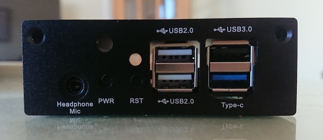
The Quartz64 model A can be made to fit this case, however some filing of one of the holes is necessary because one of the RockPro64 ports is a type-C, whereas on the Quartz64 model A all of the ports are type As.
Interference between Quartz64 model A and the case as supplied:-
Fitment once the case has been filed:-
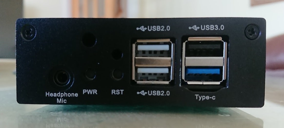
Fitment of the other end (no modification necessary):-
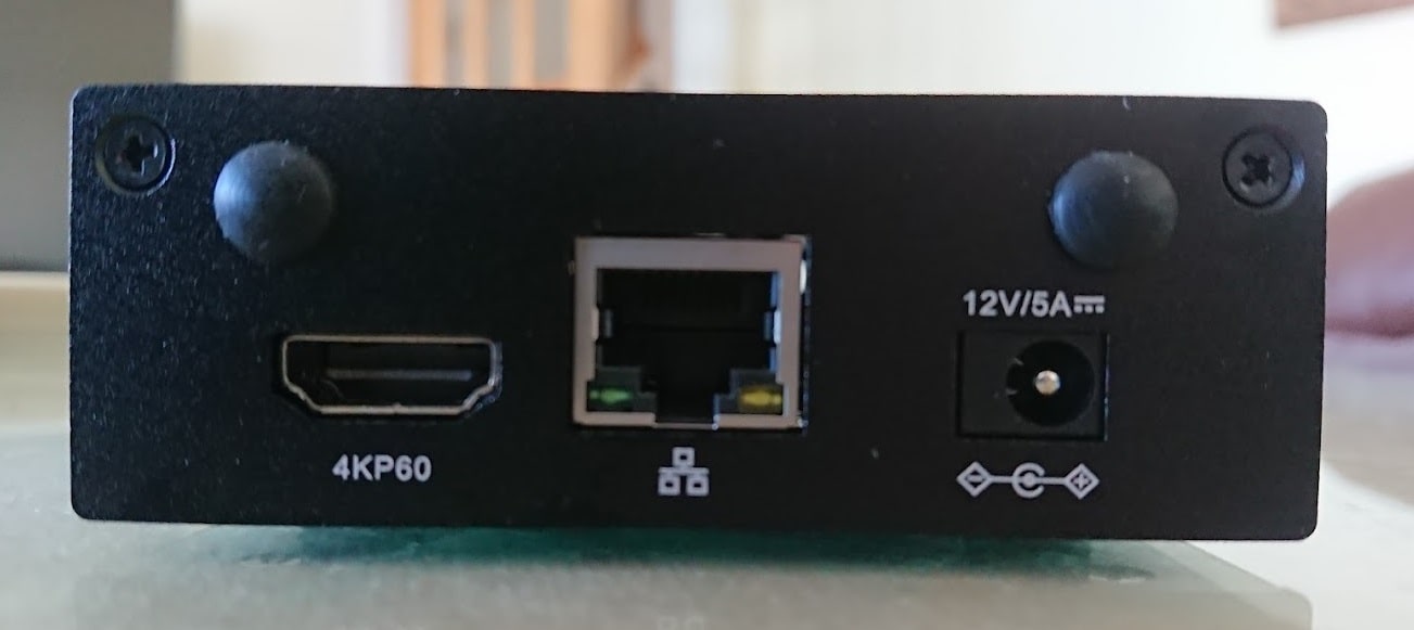
Also note that the SoC in the Quartz64-A is slightly lower than the Rock64 Pro one (apparently about 0.6mm). This case includes an internal post which (using a thermal pad) touches the SoC to transfer heat from the SoC to the case. However it does not make good contact with the RK3566. The best solution is probably to source a thicker thermal pad.
Enclosures
Note: Please expand this section with more cases known to work.
Model “A”
All enclosures that fit the ROCKPro64 should fit the Quartz64 Model “A”, as the I/O has been laid out the same on purpose.
- Model A Acrylic Open Enclosure - but see the troubleshooting section below.
- RockPro64 Premium Aluminium Case
- ROCKPro64 (Not an enclosure but allows to mount the board in an ATX/ITX case)
Model “B”
- Model B Acrylic Open Enclosure
- the ROCK64 aluminium enclosure does not work, as the DC input jack is placed differently
Further information
Datasheets
Rockchip RK3566 SoC information:
- Rockchip RK3566 ver 1.0 datasheet, already got release permission from Rockchip
- Rockchip RK3566 and RK3568 TRM (Technical Reference Manual)
Rockchip PMU (Power Management Unit) Information:
- Rockchip RK817 ver 1.01 datasheet for Quartz64 model A
- Rockchip RK809 ver 1.01 datasheet for Quartz64 model B and SOQuartz
LPDDR4 (200 Balls) SDRAM:
eMMC information:
- PINE64 eMMC module schematic
- PINE64 USB adapter for eMMC module V2 schematic
- PINE64 USB adapter for eMMC module PCB in JPEG
- 16GB Foresee eMMC Datasheet
- 32GB/64GB/128GB SanDisk eMMC Datasheet
SPI NOR Flash information:
E-ink Panel information:
- Eink 10.3" 1872x1404 ES103TC1 Flex Panel Specification
- Eink 10.3" 1872x1404 ES103TC1 Glass Panel Specification
- TPS65185x PMIC for E-Ink Enabled Electronic Paper Display Datasheet
LCD Touch Screen Panel information:
- 7.0" 1024x600 TFT-LCD Panel Specification
- Touch Panel Specification
- GOODiX GT911 5-Point Capacitive Touch Controller Datasheet
Ethernet PHY information:
Wi-Fi/BT module info:
- Azurewave CM256SM 11AC Wi-Fi + Bluetooth 5.0 datasheet for model A and B
- AICSemi AIC8800DC 11AX Wi-Fi + Bluetooth 5.2 datasheet for model “Zero”
IR LED:
Enclosure information:
- Playbox Enclosure 3D file
- ABS Enclosure 3D file
- Outdoor Aluminum Cast Dust-proof IP67 Enclosure Drawing
- 3D Printable Enclosure for Model A
- Open Frame for Model A
Connector information:
- 2.0mm PH Type connector specification use in Lithium Battery (VBAT) port (Model A)
- 1.25mm Picoblade Type connector specification used in RTC Battery port (Model B)
- 0.5mm Pitch cover type FPC connector specification use in DSI port, TP port and CSI port
Schematics and certifications
Model “A”
Model “A” Baseboard Dimensions: 133mm x 80mm x 19mm
Input Power: DC 12V @ 3A 5.5mmOD/2.1mmID center-positive Barrel DC Jack connector
Quartz64 Model “A” SBC Schematic and PCB Board Resource:
- Quartz64 Model “A” SBC Schematic ver 2.0 20210427 PDF file
- Quartz64 Model “A” SBC PCB Connector placement PDF file
Certifications:
- Disclaimer: Please note that PINE64 SBC is not a “final” product and in general certification is not necessary. However, PINE64 still submit the SBC for FCC and CE certification and obtain the certificates to proof that SBC board is capable on passing the testing. Please note a final commercial product needs to performs its owns testing and obtains its owns certificates.
- Quartz64 model-A CE Certificate
- Quartz64 model-A FCC Certificate
Model “B”
Model “B” Baseboard Dimensions: 85mm x 56mm x 18.8mm
Input Power: DC 5V @ 3A 3.5mmOD/1.35mmID center-positive Barrel DC Jack connector
Quartz64 Model “B” SBC Schematic and PCB Board Resource:
- Quartz64 Model “B” SBC Schematic ver 1.3 20220124 PDF file
- Quartz64 Model “B” SBC PCB Connector placement PDF file
- Please note that v1.2 and V1.3 schematic and component placement are identical, just some component value changed.
- Note: Model B uses a Molex PicoBlade compatible connector for the RTC battery. The Pine64 Backup Battery Holders come with a JST PH type connector. To use the Pine64 RTC Backup Battery Holder, the connector on the battery holder will need to be modified with a PicoBlade type connector.
Model “Zero”
Model “Zero” Baseboard Dimensions: 85mm x 56mm x 18.8mm
Input Power: DC 5V @ 3A 3.5mmOD/1.35mmID center-positive Barrel DC Jack connector
Quartz64 Model “Zero” SBC Schematic and PCB Board Resource:
- Quartz64 Model “Zero” SBC Schematic ver 1.0 20240428 PDF file
- Quartz64 Model “Zero” SBC PCB Component placement (top side) PDF file
- Quartz64 Model “Zero” SBC PCB Component placement (bottom side) PDF file
Specifications
- Based on Rockchip RK3566
CPU Architecture
- Quad-core ARM Cortex-A55@1.8GHz
- AArch32 for full backwards compatibility with ARMv7
- ARM Neon Advanced SIMD (single instruction, multiple data) support for accelerated media and signal processing computation
- Includes VFP hardware to support single and double-precision operations
- ARMv8 Cryptography Extensions
- Integrated 32KB L1 instruction cache and 32KB L1 data cache per core
- 512KB unified system L3 cache
- TrustZone technology support
- 22nm process, believed to be FD-SOI
GPU (Graphics Processing Unit) Capabilities
- Mali-G52 2EE Bifrost GPU@800MHz
- 4x Multi-Sampling Anti-Aliasing (MSAA) with minimal performance drop
- 128KB L2 Cache configurations
- Supports OpenGL ES 1.1, 2.0, and 3.2
- Supports Vulkan 1.0 and 1.1
- Supports OpenCL 2.0 Full Profile
- Supports 1600 Mpix/s fill rate when at 800MHz clock frequency
- Supports 38.4 GLOP/s when at 800MHz clock frequency
NPU (Neural Processing Unit) Capabilities
- Neural network acceleration engine with processing performance of up to 0.8 TOPS
- Supports integer 8 and integer 16 convolution operations
- Supports the following deep learning frameworks: TensorFlow, TF-lite, Pytorch, Caffe, ONNX, MXNet, Keras, Darknet
System Memory
- RAM Memory Variants: 2GB (SOQuartz only), 4GB, 8GB LPDDR4.
Network
- 10/100/1000Mbps Ethernet
- Wi-Fi 802.11 b/g/n/ac with Bluetooth 5.0 (optional on model A, built in on model B)
Storage
- microSD - bootable, supports SDHC and SDXC, storage up to 2TB
- USB
- Model A: 2 USB 2.0 host ports, 1 USB 2.0 OTG port, 1 USB 3.0 host port
- Model B: 1 USB 2.0 host port, 1 USB 2.0 OTG port, 1 USB 3.0 host port
- one native SATA 3.0 6Gb/s Port (only on model A, shared with USB 3.0 host port) (removed in newer revisions due to electrical signalling issues it caused)
- optional eMMC module from 8GB up to 128GB
- 64 Mbit (8 MByte) SPI flash (Model B only), part number 25Q64DWZPIG in the schematic
eMMC Speeds
On a 64 GB eMMC module:
$ sudo hdparm -tT /dev/mmcblk1
/dev/mmcblk1:
 Timing cached reads:   2368 MB in  2.00 seconds = 1184.46 MB/sec
 Timing buffered disk reads: 452 MB in  3.01 seconds = 149.98 MB/sec
Expansion Ports
- HDMI
- eDP - 4 lanes of 2.7Gbps, up to 2560x1600@60Hz (only on model A)
- DSI - Display Serial Interface, 4 lanes MiPi, up to 1440P on model A, 2 lanes MiPi, up to 1080p on model B
- CSI - CMOS Camera Interface, 4 lanes MiPi up to 8 mega pixel on model A, 2 lanes MiPi up to 5 mega pixel on model B
- TP - Touch Panel Port, SPI with interrupt on model A
- RTC - Real Time Clock Battery Connector
- VBAT - Lithium Battery Connector with temperature sensor input on model A
- Wi-Fi/BT Module Header - SDIO 3.0 and UART on model A, built-in Wi-Fi/BT Module on model B
- 2x20 pins “Pi2” GPIO Header on model B, 2x10 pins GPO header on model A
- PCIe x4 open ended slot on model A, m.2 slot on model B, one Gen2 lane due to SoC constraints
- On Model A, the slot provides 10W of power for the 3.3V supply and however much power your 12V input power supply provides on the 12V supply
The PCIe implementation on the RK3566 is much more compatible with a wide range of devices compared to the one on the RK3399 used on the ROCKPro64. This means a lot more devices should work (excluding dGPUs due to a lack of cache snooping ability).
Combo PHYs
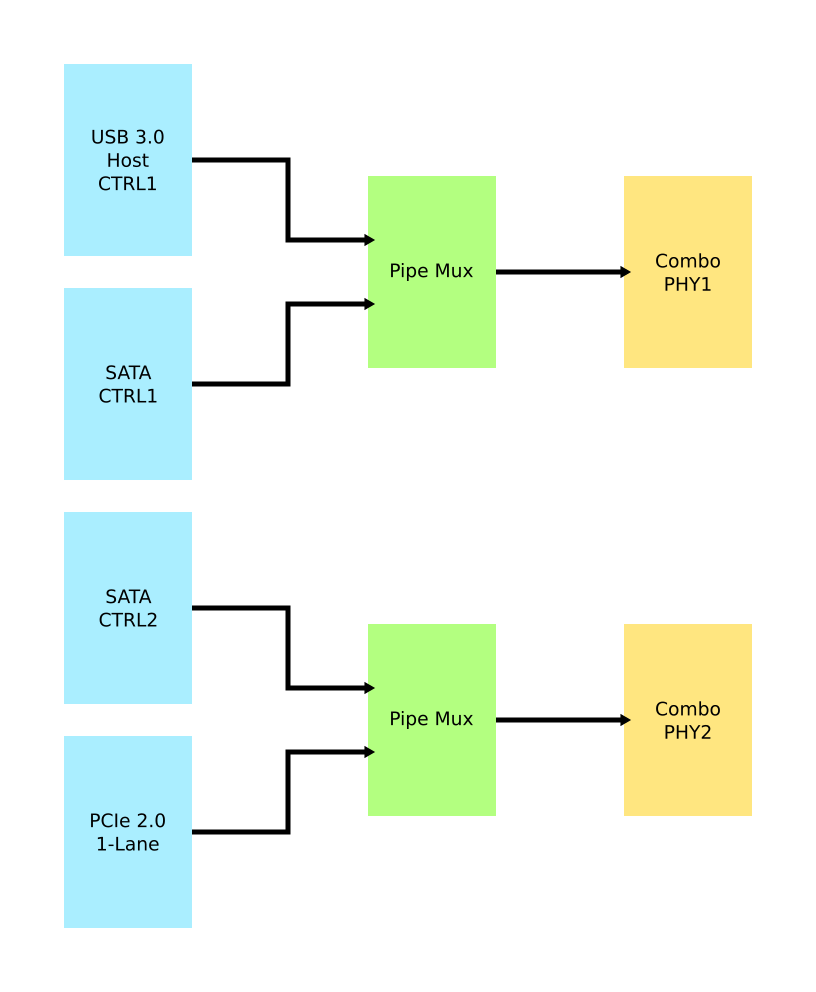
Several of the I/O options on the RK3566 used in the Quartz64 are using the same I/O lines, meaning that they cannot be used at the same time. The above diagram illustrates how they are connected.
In particular, USB 3.0 and the SATA connector on the board are mutually exclusive, and the PCI-e 2.0 lane can be reconfigured into a second SATA port, though an adapter cable needs to be fashioned for this to be useful.
GPIO Pins (Quartz64 Model A)
Attention! GPIOs are 3.3V!
| Assigned To | Pin no. | Pin no. | Assigned To |
|---|---|---|---|
| 3.3 V | 1 | 2 | 5 V |
| I2C3_SDA_M0 a,b | 3 | 4 | 5 V |
| I2C3_SCL_M0 a,b | 5 | 6 | GND |
| CPU_REFCLK_OUT | 7 | 8 | UART2_TX_M0_DEBUG |
| GND | 9 | 10 | UART2_RX_M0_DEBUG |
| SPI1_MOSI_M1 | 11 | 12 | UART0_TX a |
| SPI1_MISO_M1 | 13 | 14 | UART0_RX a |
| SPI1_CLK_M1 | 15 | 16 | GND |
| SPI1_CS0_M1 | 17 | 18 | SPDIF_OUT c |
| GND | 19 | 20 | 3.3V |
Notes
a: can be a PWM pin
b: pulled high to 3.3V through 2.2kOhm resistor
c: low-pass filtered with cutoff of 220 MHz
Source: Page 28 of the board schematics.
GPIO Pins (Quartz64 Model B)
Attention! GPIOs are 3.3V!
Interesting alternate pin configurations are listed in [brackets].
| Assigned To | Pin no. | Pin no. | Assigned To |
|---|---|---|---|
| 3.3 V | 1 | 2 | 5 V |
| [I2C3_SDA_M0] GPIO1_A0_3V3 | 3 | 4 | 5 V |
| [I2C3_SCL_M0] GPIO1_A1_3V3 | 5 | 6 | GND |
| GPIO3_C4_3V3 | 7 | 8 | UART2_TX |
| GND | 9 | 10 | UART2_RX |
| [SPI1_CS0_M1] GPIO3_A1_3V3 | 11 | 12 | GPIO3_A3_3V3 [I2S3_SCLK_M0] |
| [I2S3_MCLK_M0] GPIO3_A2_3V3 | 13 | 14 | GND |
| GPIO3_B0_3V3 | 15 | 16 | GPIO3_B1_3V3 |
| 3.3V | 17 | 18 | GPIO3_B2_3V3 |
| GPIO4_C3_3V3 | 19 | 20 | GND |
| GPIO4_C5_3V3 | 21 | 22 | GPIO3_C1_3V3 [SPI1_MOSI_M1] |
| GPIO4_C2_3V3 | 23 | 24 | GPIO4_C6_3V3 |
| GND | 25 | 26 | GPIO4_D1_3V3 |
| I2C4_SDA_M0 | 27 | 28 | I2C4_SCL_M0 |
| GPIO3_B3_3V3 | 29 | 30 | GND |
| GPIO3_B4_3V3 | 31 | 32 | GPIO3_C2_3V3 [SPI1_MISO_M1] |
| [SPI1_CLK_M1] GPIO3_C3_3V3 | 33 | 34 | GND |
| [I2S3_LRCK_M0] GPIO3_A4_3V3 | 35 | 36 | GPIO3_A7_3V3 |
| [SPDIF_TX_M0] GPIO1_A4_3V3 | 37 | 38 | GPIO3_A6_3V3 [I2S3_SDI_M0] |
| GND | 39 | 40 | GPIO3_A5_3V3 [I2S3_SDO_M0] |
Source: Page 24 of the board schematics.


